-->

Safety & Power Questions & Answers

BUILD LEARN SHARE

Turn β€œwhy won’t it work?” into your next working circuit.

Follow a practical learning path, search real troubleshooting answers, share your builds, and keep reliable bench references close at hand.

Subscriber workbench
33answered questions
10maker builds
12+learning resources
Pick a starting point

Choose your maker path

Focused guides connect the concepts, tools, and safety checks needed for a confident next build.

Maker challenge: Build a safer, cleaner breadboard power layout

Label the rails, add current limiting, verify polarity, then share one improvement you made.

Community knowledge bench

Find an electronics answer

Search by symptom, part, or project. Every editorial answer is visible for makers and search engines.

Safety & PowerTechCrate editorial answer

Photoresistor (LDR) giving weird readings in bright vs dim light

Wired up a photoresistor voltage divider like the book shows, reading it on A0. In bright light I get a low number and in the dark I get close to 1023. Is that backwards from what should happen?
TechCrate editorial answer
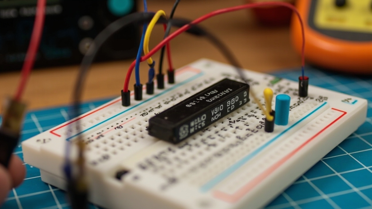
Nothing is broken β€” an LDR's resistance drops in bright light and rises in darkness, so whether A0 reads high or low in bright light just depends on whether the LDR sits on the top or bottom half of your voltage divider. Your wiring (LDR on the bottom, near GND) produces exactly the low-in-bright/high-in-dark pattern you're seeing. The voltage divider midpoint follows:

V_out = 5V Γ— (R_bottom / (R_top + R_bottom))
β€’ LDR on top (between 5V and A0), fixed resistor on bottom: in bright light the LDR resistance drops, so more of the divider's share goes to the fixed resistor β€” A0 reads HIGH in bright light.
β€’ LDR on bottom (between A0 and GND), fixed resistor on top: in bright light the LDR resistance drops, pulling A0 toward GND β€” A0 reads LOW in bright light. See the full answer β†’
Want to see the full answer with all the details?

Unlock this and 100s of resources + your personal AI circuit trainer!
Safety & PowerTechCrate editorial answer

Transistor as a switch β€” base resistor value seems arbitrary in the book

Building the transistor switch circuit (2N3904 driving a motor) and the book just says "use a 1K resistor on the base" without explaining how they got that number. If I use a different motor or transistor, how would I figure out the right base resistor myself?
TechCrate editorial answer
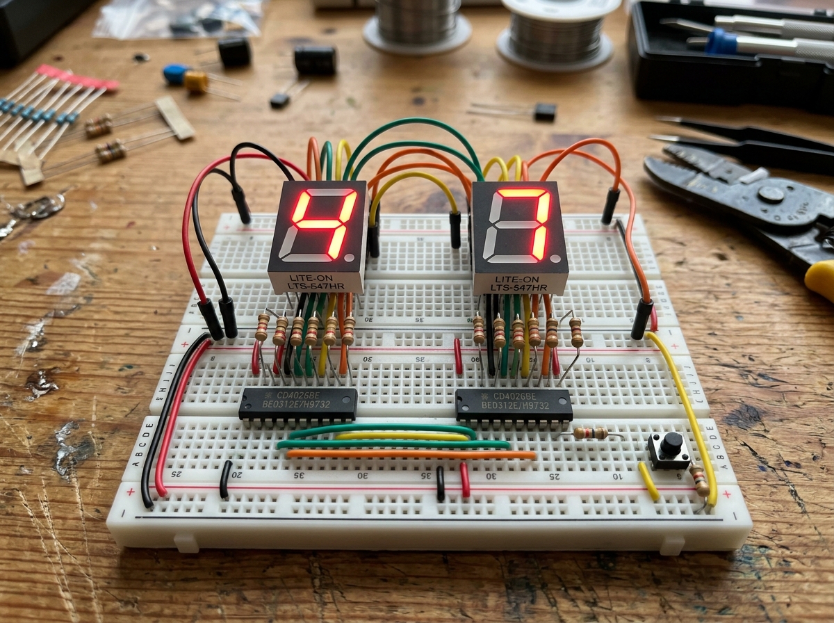
Choose a base resistor from the load current, a conservative forced current gain and the transistor’s saturation data, rather than typical hFE alone. The controller must also be able to supply the resulting base current. A motor’s starting or stalled current can exceed its running current, so size the switch for that condition. See the full answer β†’
Want to see the full answer with all the details?

Unlock this and 100s of resources + your personal AI circuit trainer!
Safety & PowerTechCrate editorial answer

Breadboard mistake β€” accidentally bridged both power rails together

I was moving jumper wires around fast and I think I bridged the positive and negative rails with a single wire without realizing until I smelled something warm. Battery pack got hot to the touch. Is my breadboard or battery ruined?
TechCrate editorial answer
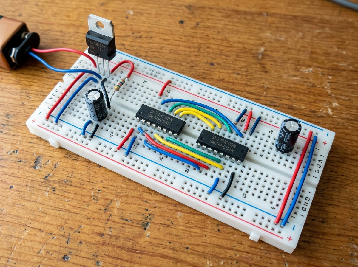
You created a dead short, and the warm smell was current maxing out through that bare wire β€” disconnect power immediately. A short can damage the battery, contacts or wiring; a brief duration does not prove they are safe to reuse. What happened: connecting the positive and negative rails with a wire and no resistor or component in between creates essentially zero resistance. By Ohm's Law (I = V/R), as resistance approaches zero, current tries to spike, and your battery pack got hot dumping as much current as it could into that wire. See the full answer β†’
Want to see the full answer with all the details?

Unlock this and 100s of resources + your personal AI circuit trainer!
Safety & PowerTechCrate editorial answer

Multimeter reads 0V everywhere even though circuit is powered

My multimeter is showing 0 volts no matter where I probe, but I can see the LED is lit so I know current is flowing. Battery snap connector is new. Am I doing something wrong with the meter itself?
TechCrate editorial answer
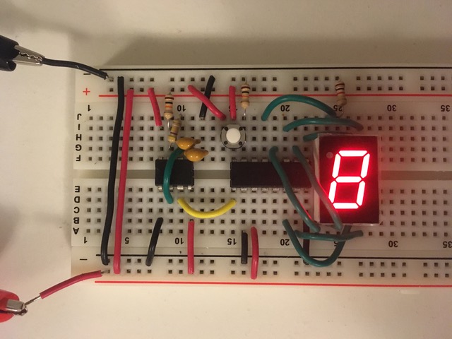
Since the LED is lit, voltage is clearly present, so this is almost certainly a meter setup issue, not a dead circuit β€” check that the dial is on a DCV range (not ACV) and that the red probe is in the VΞ©mA jack, not the 10A/20A jack. Other common culprits:

1. Dial on the wrong function. Cheap meters share dial positions between DC voltage ranges (usually marked V with a straight line or "DC") and other functions like AC volts (V with a wavy line ~). See the full answer β†’
Want to see the full answer with all the details?

Unlock this and 100s of resources + your personal AI circuit trainer!
Safety & PowerTechCrate editorial answer

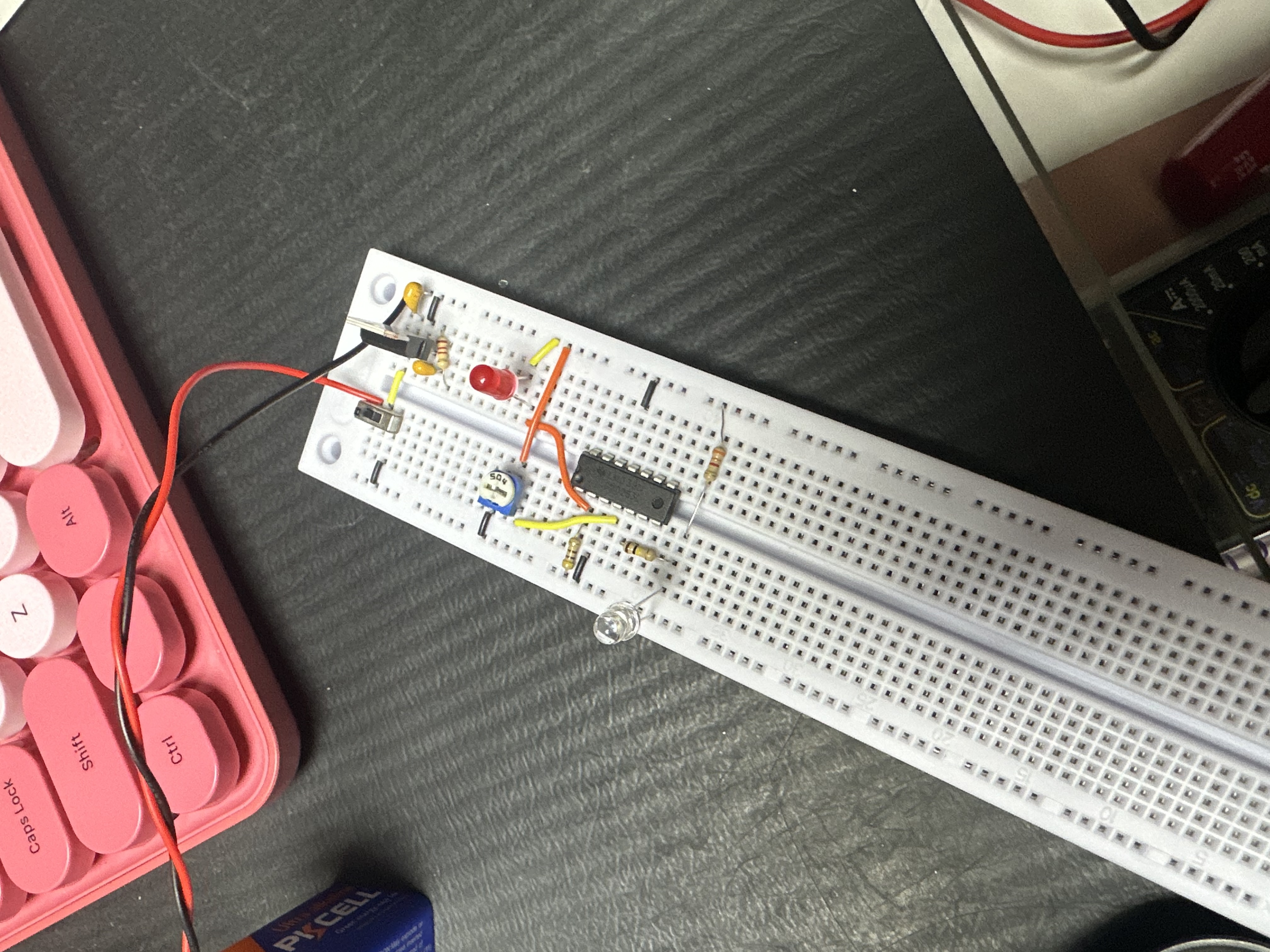
LED not lighting up at all β€” checked polarity twice

Built a simple LED + resistor circuit on the breadboard powered by a 9V battery, LED is dead, no light no matter what I try. I flipped it around thinking it was backwards but still nothing. Multimeter shows the battery is fine at 9.2V. What else could be wrong?
TechCrate editorial answer
The most likely culprit is a broken connection across your breadboard's center gap β€” the five holes on each side of that gap are electrically separate, so if the LED and resistor legs land on opposite sides without a jumper bridging them, the circuit is open even though it looks connected. Work through this checklist to confirm:

Step 1: Verify the LED itself works.
Pull it out entirely and test it directly against the battery through your resistor. If it still doesn't light, the LED may be dead (they can burn out silently if ever connected without a resistor, even briefly). Step 2: Check your breadboard rows.
Confirm the LED leg and resistor leg share the same row, or are properly jumpered across the center gap. Step 3: Confirm your resistor value isn't absurdly high.
A 1M (brown-black-green) instead of 220-330Ξ© lets so little current through the LED can appear completely dark. Double check the colour bands or measure it with the multimeter. See the full answer β†’
Want to see the full answer with all the details?

Unlock this and 100s of resources + your personal AI circuit trainer!
Want the full workbench?

Choose digital access or add the monthly hardware crate.

Digital VIP Β· $4.99/moCrate + VIP Β· $14.99/mo

Free Shipping

On orders over $50

Fast Shipping

Ships within 24 hours

Secure Checkout

256-bit SSL encrypted

Family Owned

Since 2013 in Pine Hill, NJ

Follow us for tutorials, product demos, and maker inspiration!
Added to Cart!