-->

555 Timers & ICs Questions & Answers

BUILD LEARN SHARE

Turn β€œwhy won’t it work?” into your next working circuit.

Follow a practical learning path, search real troubleshooting answers, share your builds, and keep reliable bench references close at hand.

Subscriber workbench
33answered questions
10maker builds
12+learning resources
Pick a starting point

Choose your maker path

Focused guides connect the concepts, tools, and safety checks needed for a confident next build.

Maker challenge: Build a safer, cleaner breadboard power layout

Label the rails, add current limiting, verify polarity, then share one improvement you made.

Community knowledge bench

Find an electronics answer

Search by symptom, part, or project. Every editorial answer is visible for makers and search engines.

555 Timers & ICsAnswered by ALAI (AI assistant)

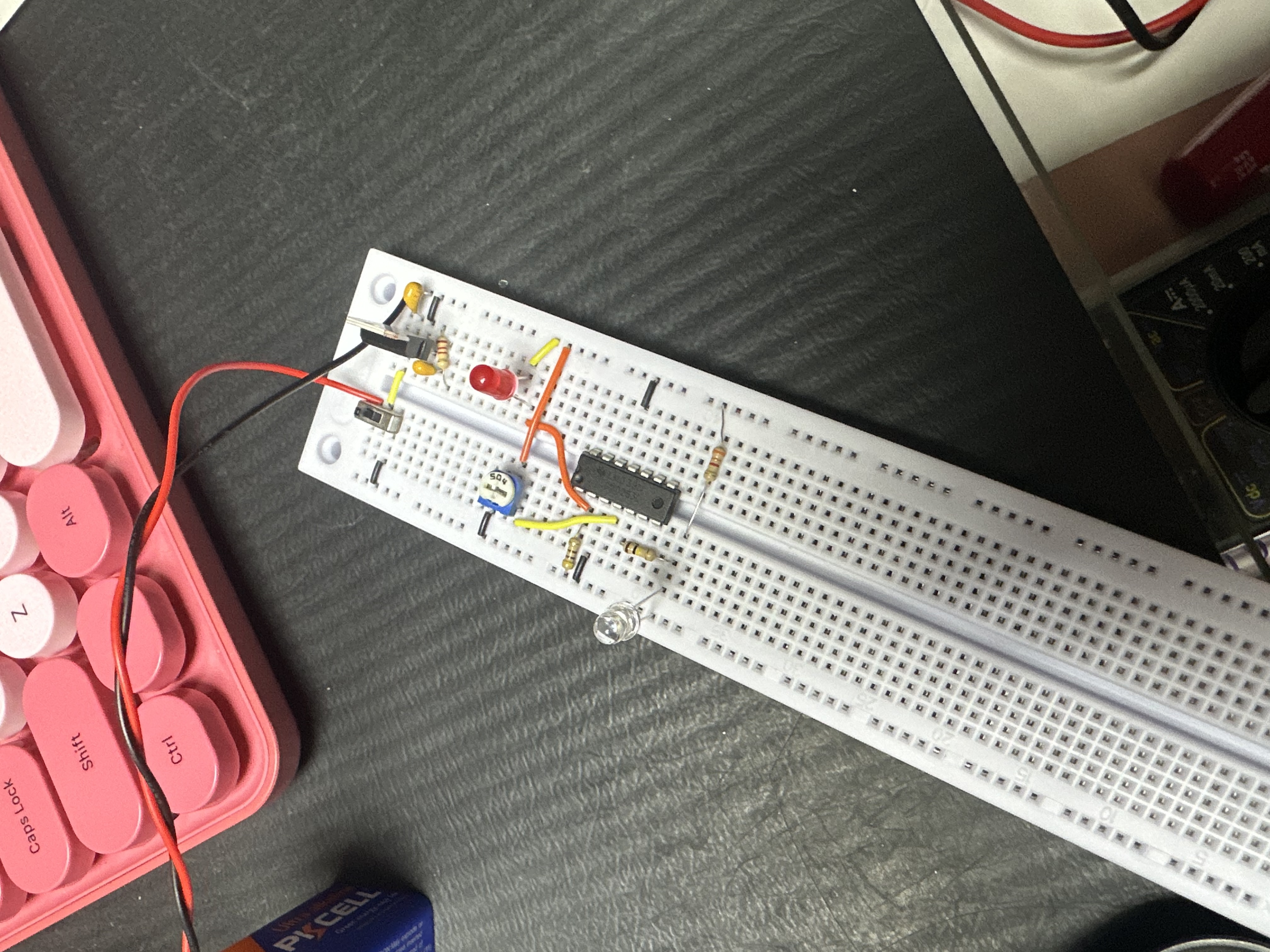
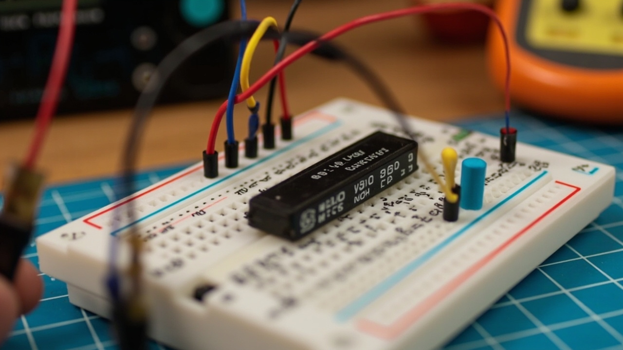
555 timer is not working with flashing led kit

555 chip
led
Answered by ALAI (AI assistant) — double-check before powering up
The 555 timer is a highly versatile IC often used in timing, pulse generation, and oscillator applications. When paired with an LED, it can be configured in various modes, such as astable or monostable, to create flashing or stable light outputs. One common cause of issues in these circuits is incorrect resistor values, which can affect the timing intervals or prevent the LED from lighting.

Be sure to observe polarity when connecting your components on a breadboard to avoid any accidental damage. Accurate use of the multimeter can verify that your connections and components are within specification. For makers seeking to diagnose their LED-timer circuit more thoroughly, exploring the full diagnostic workflow can yield rewarding insights. See the full answer β†’
Want to see the full answer with all the details?

Unlock this and 100s of resources + your personal AI circuit trainer!

555 Timers & ICsTechCrate editorial answer

Preventing Floating CMOS IC Inputs (CD4017 / CD4026)

Why does my digital counter IC behave erratically when I touch the breadboard or leave pins disconnected?
TechCrate editorial answer
CMOS digital logic ICs (like the CD4017 decade counter or CD4026 display driver) have extremely high input impedance. If an input pin (like Clock or Reset) is left floating without a connection to Power or Ground, it acts like an antenna picking up static electricity and 60Hz ambient AC noise. This causes false triggering, rapid random counting, and erratic display behavior. See the full answer β†’
Want to see the full answer with all the details?

Unlock this and 100s of resources + your personal AI circuit trainer!

555 Timers & ICsTechCrate editorial answer

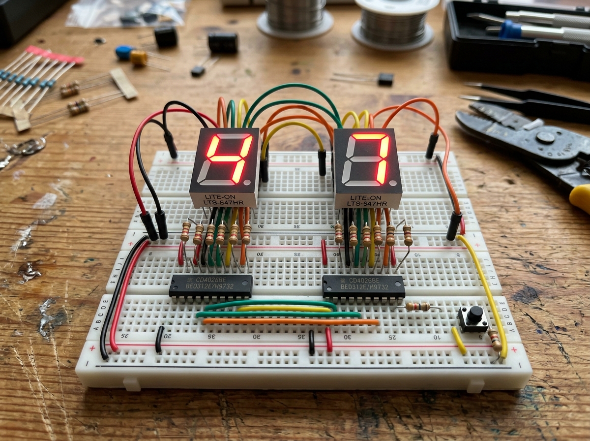
CMOS decade counter CD4026BE

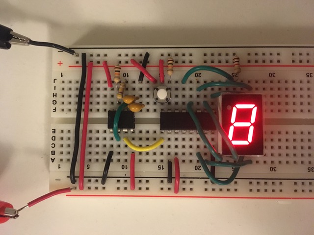
Im having so much fun with this kit! I ran into my first noob problem with the CMOS decade counter CD4026BE. I wired up this circuit from make electronics and I think I had a issue or maybe burned the IC crossing the power as the LED display lit up all segments at one point and looked like this in the end.. I may have moved wires checking my work though. this is so cool though!
TechCrate editorial answer
All segments lighting up at once on a CD4026BE-driven display is usually not permanent chip damage β€” it's most often caused by the RESET pin (pin 7) floating or being pulled HIGH unintentionally, or the DISPLAY ENABLE IN pin (pin 3) left floating instead of tied to a defined level, both of which can make the segment outputs behave erratically rather than showing a clean digit. Quick CD4026BE pinout reference (16-pin DIP):
β€’ Pin 1: Clock (counts up on each rising edge)
β€’ Pin 2: Clock Inhibit (hold LOW to allow counting)
β€’ Pin 3: Display Enable In (tie HIGH/to Vdd if you're not cascading multiple chips)
β€’ Pins 4, 5, 6: segment outputs c, d, e
β€’ Pin 7: Reset (active HIGH β€” pulls the count back to zero; must be tied LOW, not left floating, when not in use)
β€’ Pin 8: Vss (ground)
β€’ Pin 9: ungated Carry Out
β€’ Pins 10, 11: segment outputs b, a
β€’ Pins 12, 13: segment outputs f, g
β€’ Pin 14: Display Enable Out (for cascading)
β€’ Pin 15: gated Carry Out (one pulse per 10 counts, used to chain a second CD4026 for multi-digit counters)
β€’ Pin 16: Vdd (positive supply)

What to check on your breadboard: See the full answer β†’
Want to see the full answer with all the details?

Unlock this and 100s of resources + your personal AI circuit trainer!
555 Timers & ICsTechCrate editorial answer

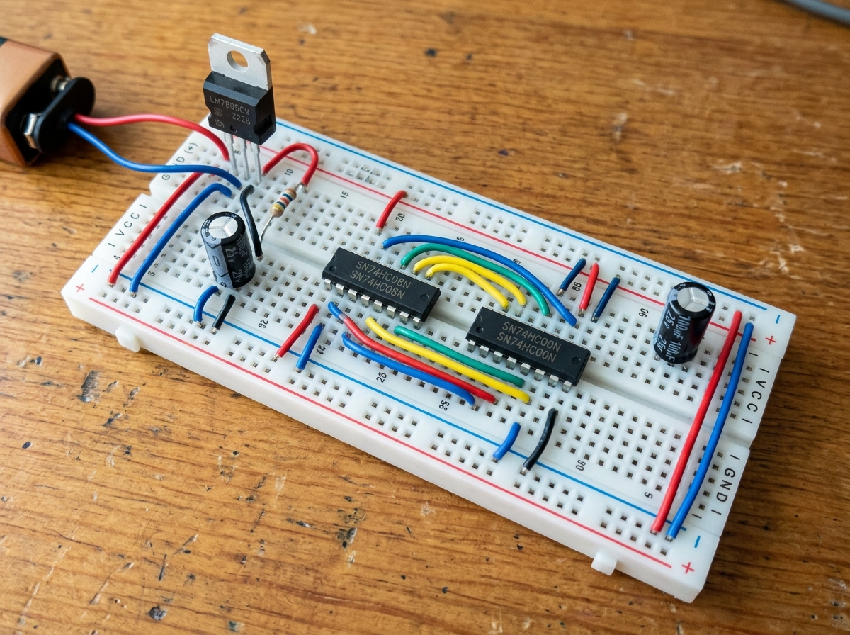
How does a 555 timer astable circuit actually decide the blink rate?

Working through the 555 timer chapter and I got the LED blinking circuit working which is awesome, but I don't really understand WHY changing the resistor values changes the blink speed. The book explains it but I'm still fuzzy on what's actually happening inside the chip.
TechCrate editorial answer
The blink rate is set by how fast your timing resistors (R1, R2) and capacitor (C) charge and discharge β€” bigger resistor or capacitor values mean slower charging, so the LED blinks slower; smaller values charge faster, so it blinks faster. Here's the full cycle happening inside the chip:

1. The capacitor charges up through R1 and R2 from the supply voltage, with the output pin HIGH during this phase. See the full answer β†’
Want to see the full answer with all the details?

Unlock this and 100s of resources + your personal AI circuit trainer!
Want the full workbench?

Choose digital access or add the monthly hardware crate.

Digital VIP Β· $4.99/moCrate + VIP Β· $14.99/mo

Free Shipping

On orders over $50

Fast Shipping

Ships within 24 hours

Secure Checkout

256-bit SSL encrypted

Family Owned

Since 2013 in Pine Hill, NJ

Follow us for tutorials, product demos, and maker inspiration!
Added to Cart!