
Free beginner workbench
Why is my breadboard circuit not working?
Seven ordered checks for a dark LED or silent breadboard circuit, with one worked voltage example.
A circuit that does nothing is giving you information, even if it is not the information you wanted. Rebuilding it at random throws away that evidence. This exercise uses a small LED circuit to show an ordered diagnosis: establish the supply, establish the hidden connections, then follow the current path. It assumes a documented low voltage hobby circuit. Disconnect immediately if you see smoke, smell burning or feel unexpected heat; do not troubleshoot a hot circuit while it remains powered.
1. Return to a known drawing
Disconnect the battery or adapter. Place the schematic and the parts list beside the board. Identify what should happen and which part is not doing it. Record the actual source and component values rather than relying on memory. An overhead photograph before moving anything can preserve the mistake you are trying to understand. Remove unrelated experimental additions so that there is one documented version to compare.
2. Check the source at the load
With the meter correctly set for DC voltage, confirm source polarity and the expected voltage. Then check at the circuit's own supply and ground nodes when it is safe to apply power. A voltage measured on a disconnected battery is not proof that it will hold up under load. A switched off adapter, loose battery clip or poor jumper can give a normal reading at one point and nothing at the board. Disconnect again before changing wiring.
3. Map the hidden connection groups
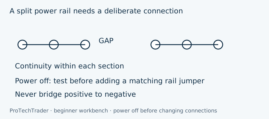
The stripes on a breadboard are labels, not electrical guarantees. With power disconnected, use continuity mode to identify which holes belong together. Check whether each long power rail is broken halfway along its length, whether opposite sides are connected, and where the centre gap separates terminal strips. The existing breadboard guide explains that layout in detail. This check is about proving your particular board rather than repeating its generic drawing.
4. Trace the ground return
Every ordinary powered loop needs a return path. Follow source positive through the load and back to source negative. Ground on a schematic represents an intended common reference; it does not make separated rails magically connect. Check a return jumper at both ends. An LED and resistor can be arranged neatly while the final return hole is one group away from the battery negative connection.
5. Confirm orientation and value
Read resistor bands, LED polarity, capacitor markings and the chip notch against the actual package drawing. A resistor is not polarised, but its value matters. An integrated circuit placed along one connected strip can short terminals together; a DIP normally straddles the centre gap. For a 555, a disconnected RESET connection can prevent oscillation even when the supply is correct. Use the circuit guide to check required pin connections rather than copying a photograph of a different project.
6. Inspect each mechanical connection
Look for insulation trapped in a contact, a jumper inserted beside its intended hole, bent chip legs and leads that do not reach the spring contacts. Tug gently with power off. Verify continuity from the actual component lead to the intended node if a visual inspection is inconclusive. Move one suspect connection at a time, recording what changed. A loose contact that temporarily works when pushed is still a fault to repair.
7. Measure one useful node and compare
Reconnect only after the power-off checks pass. Choose a measurement with a clear prediction. For a red LED exercise using 5 V, an assumed 2 V LED drop and 330 Ω, expect about 3 V across the resistor. Ohm's law gives I = V/R = 3/330 = 0.009091 A, about 9.09 mA. This lets you estimate current from a voltage measurement without opening the loop to insert an ammeter.
If you measure nearly no voltage across the resistor, that can mean no current, but it does not identify the cause by itself. A broken return, missing source or reversed LED are different possibilities. If nearly the whole supply appears across the resistor, investigate the LED connection and possible short before continuing. Compare multiple node readings with the schematic. Disconnect before repositioning a part; a slipped probe can create a fault of its own.
Common mistakes
- Using continuity or resistance mode on a powered board.
- Placing a current meter directly across the supply rails.
- Assuming both halves of a long rail are connected.
- Changing several wires and losing track of which change helped.
- Calling a component faulty before checking its actual connections.
What to ask next
Write down the intended result, the supply voltage measured at the board, the component values and the most useful node readings. Take a clear overhead photograph showing both rails and the chip notch. Ask ALAI about that evidence, not just “it does not work.” The helper can suggest another check, but its advice still needs comparison with the guide and component datasheets before power-up.
Volume 001 provides a useful timer and LED project for practising these habits, with a breadboard and power accessories supplied from the Starter Kit rather than repeated in every volume. The linked store board is a separate option if you need one. Follow the meter guide for lead sockets and modes. Stop once the circuit works consistently and record the cause; that small note often prevents the same mistake on your next build.
Continue at your workbench
ALAI is a member AI assistant and can be wrong. Digital VIP or an active TechCrate subscription is required for member answers. Low voltage hobby electronics only; no mains work.
