
Free beginner workbench
Which way round? LED, capacitor and diode polarity
Identify LED leads, aluminium electrolytic markings and diode cathode bands before powering a beginner circuit.
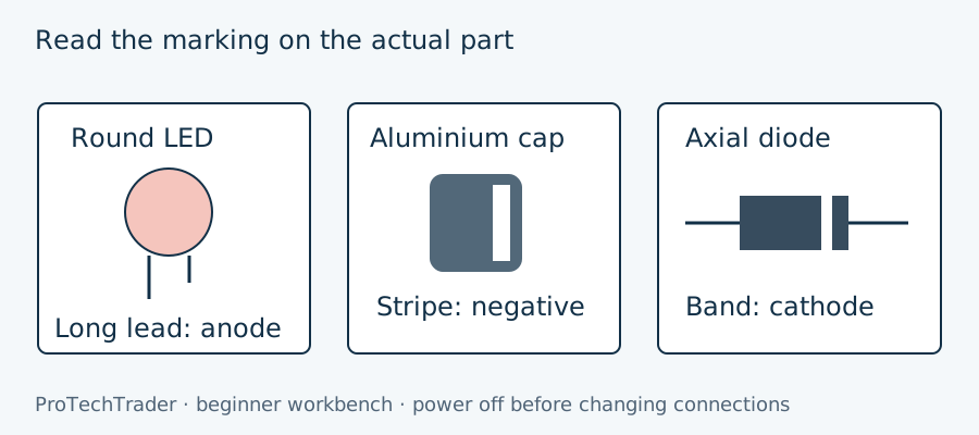
Some components work in either direction; others must face a particular way. A fixed resistor generally has no polarity, but an LED, a common aluminium electrolytic capacitor and a rectifier diode do. The markings are different because the parts do different jobs. This lesson builds a habit of identifying the actual package before connecting power. It does not ask you to identify an unknown part by colour or shape alone.
Begin with the circuit, then the marking
Disconnect the source and find the component in the circuit drawing. Label its intended connections on paper. Find the corresponding terminals in the manufacturer's package drawing or the labelled kit instructions. Only then place the part. Anode and cathode names stay attached to the physical terminals; describing a terminal simply as positive or negative can be confusing when a diode is deliberately reverse biased.
Photograph the package markings before shortening leads. Once a lead has been trimmed, its relative length is no longer reliable evidence. For a replacement part, confirm that its electrical ratings and pin arrangement match as well as its appearance. A larger package is not a promise of the correct voltage rating, and a similar looking diode is not necessarily suitable for the same circuit.
An ordinary indicator LED
On many round through hole LEDs, the longer original lead is the anode and the flat on the rim marks the cathode. These are useful clues, not a substitute for the part drawing. For forward operation, current goes from anode to cathode. In a simple indicator the anode faces the supply through a resistor and the cathode returns to ground. Multi lead, flashing and integrated driver LEDs need their own instructions.
Always include current limiting. As a worked example, assume a 5 V source, a red LED with 2 V forward drop and a 330 Ω series resistor. The current estimate is I = (5 − 2) / 330 = 0.009091 A, about 9.09 mA. Resistor power is 3² / 330 = 0.0273 W. These estimates assume those voltages; check the real LED's permitted current. Turning an LED around is not a safe way to limit current because its allowed reverse voltage may be small.
A radial aluminium electrolytic
The contrasting body stripe on a normal radial aluminium electrolytic marks its negative terminal. The longer original lead is normally positive. Put the positive terminal at the more positive voltage in the documented circuit. For a timing capacitor between a positive timing node and ground, that normally means positive at the node and negative at ground. Read the rated voltage printed on its body and choose a rating above the highest expected voltage across it.
Do not transfer that stripe rule blindly to every capacitor technology. Some tantalum packages mark the positive end. Ceramic capacitors commonly have no polarity at all. If you cannot identify the type, stop and look up the exact marking. An electrolytic connected backwards can leak, heat or vent. Disconnect immediately if the part warms or behaves abnormally; do not keep trying it to see whether it settles down. Capacitors can retain charge after the supply is removed.
A diode's band is its cathode
On many axial rectifier and switching diodes, the painted end band identifies the cathode. The diode symbol's bar represents that same cathode. An ordinary forward current path runs from the anode toward the cathode, but a protection diode can be intentionally wired to block during normal operation. Follow the specific circuit rather than assuming the stripe always goes to ground or always goes to positive.
A meter's diode mode can help check an isolated diode's forward direction. For many meters the red probe supplies the positive test voltage, but confirm your instrument's instructions. A silicon diode may show a forward voltage and the reverse direction may show an open reading. Some meters cannot light higher voltage LEDs. Neither a continuity beep nor a guessed forward drop certifies an unknown part's ratings or a capacitor's polarity.
Common mistakes
- Trusting lead length after both leads have been cut.
- Applying the aluminium capacitor stripe convention to tantalum parts.
- Treating a diode band as a universal ground marker.
- Testing polarity by repeatedly powering a suspect assembly.
- Forgetting the LED resistor because the LED lit briefly once.
Make a polarity checklist
Before power-up, point to each polarised component and state its terminal names and destination nodes. Check the supply clip as well; correct component placement does not rescue reversed supply rails. If the diagram and package seem to disagree, keep power disconnected and ask for help with both visible. Good photographs include the stripe, the chip or diode marking and the whole surrounding current path.
Volume 001 has red LEDs and a capacitor, while Volume 002 includes electrolytic capacitors for its audio project. The separate diode pack linked below is a comparison part, not a claim that either volume includes rectifier diodes. Use the existing component and semiconductor guides for a broader reference, and the LED calculator to check your indicator's current before moving on. Identifying terminals carefully once is much easier than diagnosing several damaged parts later.
Continue at your workbench
ALAI is a member AI assistant and can be wrong. Digital VIP or an active TechCrate subscription is required for member answers. Low voltage hobby electronics only; no mains work.
Existing guides for the background
- Component Reference Guide
- Semiconductor Components Guide - Transistors, Diodes & ICs Expla
- How to Use a Digital Multimeter for Electronics
