
Free beginner workbench
Blink an LED with a 555 timer
Pick R1, R2 and C for a roughly one hertz 555 astable, with charging, discharging and a complete pin checklist.
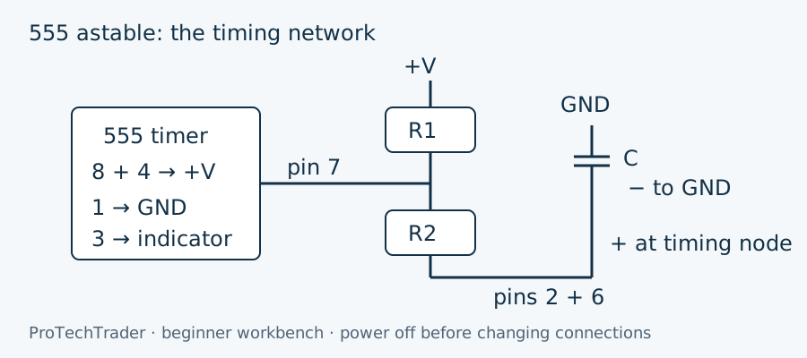
A 555 in astable mode repeatedly charges and discharges a capacitor. Its output changes state at the capacitor's threshold crossings, so an LED connected through a resistor can blink without a program. This lesson chooses values for about one full cycle per second. It is a separate standard astable exercise, not a substitute schematic for a TechCrate volume. Use a known genuine timer and its own datasheet; similar names do not guarantee identical supply or output limits.
Why the capacitor sets the pace
In the usual astable, the capacitor charges through R1 plus R2. When its voltage reaches approximately two thirds of the supply, the internal discharge switch at pin 7 turns on. The capacitor then discharges through R2, without R1 in that discharge path. At approximately one third of the supply, the switch opens and charging begins again. Output pin 3 is high during charging and low during discharging.
The capacitor moves between those two thresholds rather than starting from zero on every cycle. That is why the timing equations contain the factor ln(2), about 0.693. Increasing either timing resistance or capacitance slows the cycle. Increasing R1 also increases the proportion of time spent high. In this basic arrangement the high time exceeds the low time; equal resistor values do not produce an exactly equal on and off blink.
A worked one hertz choice
Use R1 = 10 kΩ, R2 = 68 kΩ and C = 10 µF. Convert before calculating: R1 is 10,000 Ω, R2 is 68,000 Ω and C is 0.000010 F. The period T = ln(2) × (R1 + 2R2) × C = 0.693147 × 146,000 × 0.000010 = 1.0120 seconds. Frequency f = 1/T = 0.9881 Hz, reasonably called about 1 Hz, not exactly 1 Hz.
The high time is ln(2) × (R1 + R2) × C = 0.5407 seconds. The low time is ln(2) × R2 × C = 0.4713 seconds. Adding them gives 1.0120 seconds again. Duty cycle is (R1 + R2) / (R1 + 2R2) = 78/146 = 0.5342, or 53.42%. The often quoted frequency shortcut 1.44 / ((R1 + 2R2) × C) rounds the constant and gives 0.9863 Hz here. That small difference is rounding, not a wiring fault.
Real electrolytic capacitors have tolerances and leakage. A measured blink will not necessarily match those nominal figures. Count several complete cycles and divide elapsed time by the cycle count, rather than treating one eyeballed flash as a precision measurement. One complete cycle includes both the lit and unlit intervals. The first interval after connection can differ from the later repeating intervals.
Connect with power disconnected
For an ordinary eight pin DIP 555, looking down on the package, identify the notch and follow the manufacturer's pin numbering. Connect pin 1 to ground, pin 8 to the positive supply, and pin 4 RESET to that same positive supply. Join pins 2 and 6 as the timing node. Connect R1 from positive supply to pin 7, and R2 from pin 7 to the timing node. Connect the timing capacitor from the timing node to ground, positive lead at the node if it is a polarised electrolytic.
Place a 100 nF ceramic bypass capacitor close between pins 8 and 1. A 10 nF capacitor from pin 5 to ground is the usual control pin bypass. Use a documented suitable supply, such as 5 V for the referenced standard timer circuit, and capacitors with voltage ratings above the supply. Connect pin 3 through a 1 kΩ resistor and an ordinary red LED to ground, LED cathode toward ground. Output high is not exactly the supply voltage, so its indicator current is only approximate.
Common mistakes
- Leaving RESET floating rather than tying it high.
- Putting a resistor where the timing capacitor should join ground.
- Using microfarads as farads in the calculation.
- Missing the link between pins 2 and 6.
- Counting only the bright interval as a whole cycle.
Recheck supply polarity, the chip notch and the timing capacitor before connecting power. Disconnect immediately if anything becomes hot. Use the calculator to compare the nominal result, and ask ALAI with a clear overhead picture if the circuit does not oscillate. Volume 001 includes a timer, LEDs and a timing capacitor; Volume 002 also includes timers and capacitors. These example resistor values may require extra parts. For pin functions and the standard astable equations, consult the manufacturer's 555 datasheet.
Continue at your workbench
ALAI is a member AI assistant and can be wrong. Digital VIP or an active TechCrate subscription is required for member answers. Low voltage hobby electronics only; no mains work.
