
Free beginner workbench
How to read resistor colour bands
Read four and five band resistors, work out resistance and tolerance, and check the result with a meter.
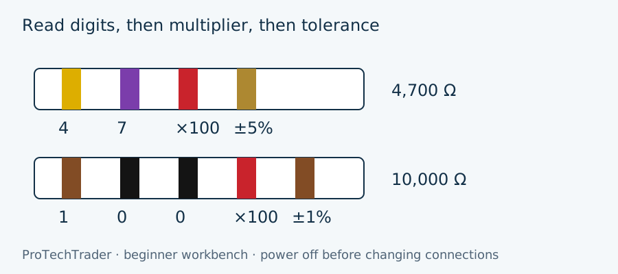
A resistor's bands describe a nominal resistance and a tolerance. They do not describe its orientation in your circuit: an ordinary fixed resistor can work either way round. Reading its body correctly matters because a multiplier error can turn a useful current limiter into something hundreds of times too large or too small. This bench exercise concentrates on decoding and checking two examples. The existing component reference remains the place for a broader tour of part types.
Find the reading direction
Use good white light and a plain background. A tolerance band is often set apart from the others. On a common four band part, gold or silver is usually at the tolerance end, so start at the opposite end. Do not apply that shortcut to every resistor: a five band precision part can have a brown tolerance band, and some parts include an additional temperature coefficient band. Confirm the series or supplier documentation if the spacing and colours are ambiguous.
Count actual painted bands before doing arithmetic. A dark brown band can resemble black in a phone photograph. Rotate the resistor without changing the reading direction, and compare it with another part from the labelled packet. A camera's automatic colour balance can distort violet, blue and grey. If the markings remain uncertain, measure the isolated resistor rather than choosing the interpretation you hoped to find.
The colour digits
For the significant digits, black means 0, brown 1, red 2, orange 3, yellow 4, green 5, blue 6, violet 7, grey 8 and white 9. The multiplier uses those same powers of ten: black is ×1, brown ×10, red ×100, orange ×1,000 and so on. Gold as a multiplier is ×0.1 and silver is ×0.01. Gold at the tolerance end usually means ±5%; silver means ±10%; brown means ±1%.
That distinction between position and colour is essential. A gold multiplier does not mean a five percent multiplier, and a red digit is not automatically a hundred ohms. Write the significant digits first, then the multiplier, then the tolerance as separate fields. This makes a mistaken reading easier to spot before a part goes into a live circuit.
Worked four band example
Yellow, violet, red, gold means the digits 4 and 7, followed by ×100, followed by ±5%. The nominal resistance is 47 × 100 = 4,700 Ω, commonly written 4.7 kΩ. Its marked tolerance amount is 4,700 × 0.05 = 235 Ω. Subtract and add that amount: the stated range is 4,465 Ω to 4,935 Ω.
A measured 4,680 Ω is inside that range. A reading near 47,000 Ω is a clue to revisit the multiplier or the meter display; it is not a small tolerance difference. The k on a display means thousands, while M means millions. A resistance reading is meaningful only when the part is not being biased by a power source or by other components connected around it.
Worked five band example
Brown, black, black, red, brown uses three significant digits: 100. Red multiplies by 100, producing 100 × 100 = 10,000 Ω, or 10 kΩ. The final brown band marks ±1%. The tolerance amount is 10,000 × 0.01 = 100 Ω, so the marked interval is 9,900 Ω to 10,100 Ω. Treating this as a four band part loses a digit and changes the answer.
The general calculation is significant number × multiplier. For a tolerance percentage t, the lower bound is R × (1 − t/100) and the upper bound is R × (1 + t/100). A meter also has its own uncertainty, so a value at the edge deserves a check against the meter specification. Tolerance describes the manufactured part under stated conditions; it is not a claim that every instrument must show exactly that number.
Common mistakes
- Starting at the tolerance end simply because it is closest to your hand.
- Reading five bands using the four band rule.
- Forgetting the multiplier after writing the first digits.
- Measuring resistance with power connected.
- Measuring in circuit and mistaking a parallel path for a bad resistor.
Make the reading useful
Disconnect power, discharge capacitors safely, and lift one resistor lead if other paths would affect the measurement. Use the meter's resistance function with the leads in the correct sockets. Avoid holding both metal probe tips with your fingers during a high resistance measurement. Compare the reading with your calculated interval and record both the nominal and measured value.
Try both examples in the resistor colour calculator, then decode a resistor from your own labelled packet. TechCrate Volume 003 lists 1 kΩ and 4.7 kΩ resistors, making it a useful place to practise distinguishing values before building its audio circuit. The five band teaching example is a separate comparison, not a claim about which resistor construction that volume supplies. Ask for help with a clear photograph if a band is unreadable, and keep the circuit disconnected until the value is resolved.
Continue at your workbench
ALAI is a member AI assistant and can be wrong. Digital VIP or an active TechCrate subscription is required for member answers. Low voltage hobby electronics only; no mains work.
