
Free beginner workbench
What resistor do I need for an LED?
Choose an LED resistor for 9 V, 5 V or 3 V, check current and power, and build a simple indicator safely.
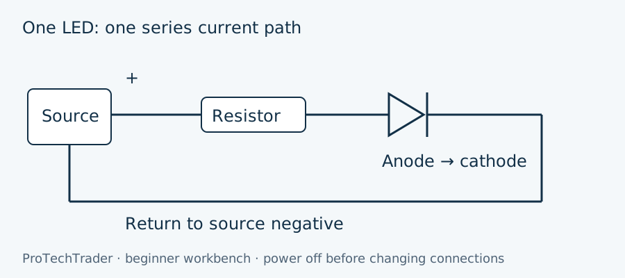
A bare LED needs something to limit its current. For a simple indicator powered by a battery or a regulated DC supply, a series resistor is usually the easiest choice. The resistor and LED carry the same current; placing the resistor before or after the LED in that single path makes no difference. This exercise is about one ordinary red indicator, not high power lighting, addressable LEDs, or an LED module with its own electronics.
Start with the LED, not a favourite resistor
Look up the forward voltage and intended operating current for the actual part. Forward voltage changes with current, temperature and manufacturing variation. Colour alone cannot give an exact value. We will assume a red LED drops 2 V and aim for 10 mA, written as 0.010 A. Those are teaching assumptions, not universal ratings. A modern efficient indicator may be bright enough at a lower current; stay below its documented limit.
Measure the source voltage if you can. A battery described as 9 V does not remain exactly there throughout its life, and a regulated USB source is a different supply again. Design for the highest expected voltage and the lowest plausible LED forward voltage when checking maximum current. Do not connect the LED directly to a battery just because it is small. A battery's internal resistance is not a dependable LED current regulator.
Work the three examples
The formula is R = (Vsupply − Vforward) / I. Put volts in the numerator and amperes in the denominator; the result is ohms. At 9 V, R = (9 − 2) / 0.010 = 700 Ω. Choosing the next higher E12 value, 820 Ω, gives I = 7 / 820 = 0.008537 A, or about 8.54 mA. The brightness change from rounding upward is usually acceptable for an indicator.
At 5 V, R = (5 − 2) / 0.010 = 300 Ω. A 330 Ω resistor gives 3 / 330 = 0.009091 A, about 9.09 mA. At 3 V, R = (3 − 2) / 0.010 = 100 Ω, already an E12 value, giving 10 mA under the stated assumptions. The smaller voltage margin makes this last circuit more sensitive to changes in the battery or LED. A blue or white LED may not have enough voltage headroom on that source.
Power matters too. Use P = I²R, or equivalently the resistor voltage squared divided by resistance. The 9 V example dissipates 7² / 820 = 0.0598 W. The 5 V example gives 3² / 330 = 0.0273 W. The 3 V example gives 1² / 100 = 0.0100 W. Each is below a quarter watt under these assumptions. Leave margin for tolerances and temperature rather than choosing a rating that only just passes.
Build and check one current path
Disconnect the source while arranging the parts. Connect source positive to the resistor, the resistor to the LED anode, and the LED cathode to source negative. The longer untrimmed lead is normally the anode; the flat edge commonly marks the cathode, but confirm the package drawing. Put the two LED leads in different breadboard connection groups so they are not shorted together underneath.
Before applying power, trace that complete loop with a finger. Read the resistor again. Check the battery clip polarity and whether the rail is split. On power-up the LED should light steadily. If it stays dark, disconnect before moving leads. Verify supply voltage, polarity and continuity methodically. Never put a meter in current mode straight across the supply; that can create a short. The existing meter guide explains safe measurement connections.
Common mistakes
- Entering milliamps as amperes and selecting a resistance far too small.
- Using a resistor colour guess without checking the multiplier band.
- Assuming every red LED has exactly the example's forward voltage.
- Connecting several parallel LEDs behind one shared resistor. Give each branch its own current control.
- Changing the supply voltage without recalculating resistance and power.
Try a useful comparison
Use the LED resistor calculator below with each supply and compare its suggested standard value with your hand calculation. If a calculator targets a different current, change the input before comparing answers. Record the actual resistance, supply voltage and observed brightness in a notebook. A dim but stable LED is a better first result than a bright damaged one.
TechCrate Volume 001 includes red LEDs and resistors in its crossing signal project. Its supplied values serve that project's wiring; this separate indicator exercise does not replace the kit guide or promise that every example value is in the box. For the broad component reference and breadboard layout lesson, use the existing guides linked below rather than guessing the hidden connections.
Continue at your workbench
ALAI is a member AI assistant and can be wrong. Digital VIP or an active TechCrate subscription is required for member answers. Low voltage hobby electronics only; no mains work.
Existing guides for the background
- Component Reference Guide
- How to Use a Breadboard: Beginner Electronics Guide
- How to Use a Digital Multimeter for Electronics
