Welcome to the TechCrate STEM & Electronics Community!
Browse member project showcases, read past ALAI AI circuit troubleshooting answers, and access electronics pinout guides below. Subscribe to unlock asking custom AI questions, full step-by-step video guides, downloadable code, and full community posting privileges!
- ā 24/7 Unlimited ALAI AI Circuit & Code Assistant
- ā Full HD Step-by-Step Video Experiment Library
- ā Downloadable PDF Lab Guides & Arduino Source Code
- ā Post Project Showcases & Participate in Community
- ā ALL Digital VIP Pass Features Included FREE
- ā Monthly Physical STEM Electronics Hardware Crate
- ā Real Components, Microcontrollers & Sensors Shipped
- ā Free Shipping Directly to Your Door
Ask ALAI AI Assistant
Ask ALAI Circuit Questions
Log in or sign up to consult our AI electronics expert with breadboard photo analysis!
**Why the LED dims:** brightness follows **I = (V_supply ā V_LED_drop) / R**. As the battery voltage sags, that shrinking numerator directly reduces LED current, so it dims ā exactly as the math predicts, not a fault.
**Why the blink rate can slow too:** if you're running a 555 timer astable circuit, the oscillation frequency is set by the RC time constant and is largely independent of supply voltage ā one of the 555's strengths. A slowdown alongside dimming can still happen because:
1. Very low supply voltages near the bottom of the 555's range (roughly 4.5-16V for a standard NE555) can introduce small timing shifts in some chip variants.
2. A partially discharged 9V battery has **higher internal resistance**, so the effective voltage reaching your circuit under load can sag further than the 7.5V you measure at rest.
3. If your blinker is a simple RC + transistor relaxation oscillator rather than a 555, those designs tend to be more voltage-dependent in their timing.
**Bottom line:** this is your circuit correctly responding to a weakening power source. Swap in a fresh battery and you should be right back to the original blink rate and brightness.
**Other low-tech options:**
1. **Compare against a known reference wire.** Standard breadboard jumper wire is typically **22 AWG** solid core. Compare thickness against any other labeled wire you have.
2. **The breadboard fit test ā the most practical method for your use case:**
- **Too loose / falls out easily** ā too thin (24-26 AWG or thinner), may not make reliable contact.
- **Fits snugly and holds position** ā right range, typically 20-22 AWG.
- **Hard to insert, or bends/kinks the holes** ā too thick (18 AWG or heavier), can damage the spring contacts over repeated use.
3. **Rough measurement with a ruler.** Strip a short length, lay 10 strands of bare wire tightly side by side against a ruler, measure total width, divide by 10 for an estimated single-strand diameter (22 AWG ā 0.64mm, 20 AWG ā 0.81mm, 24 AWG ā 0.51mm).
4. **A cheap wire gauge tool** (a few dollars) removes the guesswork if you'll be working with mixed spools regularly, but it's not required for the Make: Electronics experiments.
For breadboard prototyping specifically, the fit test is honestly all you need.
Specifically I am having trouble figuring out where to connect the components in Figure 2-118 to the breadboard. They are meant to replace the 4 color components at the lower right of Figure 2-116 / 2-117.
I am able to generate sound by guessing where to connect the speaker, 100uF capacitor, and 1K resistor, but the capacitor and resistor have no bearing on the sound..... it makes the buzz whether those components are attached or not. Also, replacing the 100uF capacitor with a 1uF capacitor as the upper portion of Figure 2-119 instructs does not change the character of the sound, so clearly I am not putting things in their proper places.
Obviously this is an issue of being able to translate schematics to functional design, but as a complete beginner on page 96 of an introductory electronics book, I find this very difficult.
Could someone please help me figure out Figure 2-118? I also foresee difficulty with the lower portion of Figure 2-119.

**Why this arrangement:** your multivibrator circuit is an oscillator producing a continuous square wave riding on top of a DC voltage. Feeding that DC straight into a speaker causes continuous current flow that isn't ideal and can reduce sound quality or damage the speaker over time. The 100uF capacitor is a **coupling capacitor** ā it charges up to the DC level and then only lets the changing AC part through, which is the actual sound signal. The 1K resistor limits how much current can flow through that path, protecting both the transistor and the speaker.
**Connection sequence:**
1. Connect one lead of the **1K resistor** to the oscillating output point (the collector of the relevant output transistor).
2. Connect the other lead of the resistor to the **positive (+) lead of the 100uF capacitor**.
3. Connect the **negative (-) lead of the capacitor** to one lead of the **speaker**.
4. Connect the other speaker lead to the **negative power rail (ground)**.
Electrolytic capacitors are polarized ā the positive lead (longer, or without the stripe) goes toward the higher-voltage output side, and the negative lead (shorter, with the stripe) goes toward the speaker/ground side.
**Why your current setup buzzes regardless of the components:** if the speaker is making sound with or without the resistor and capacitor in place, it likely means the speaker is connected directly to an oscillating point rather than through the coupling network ā it'll make noise either way, but not the intended, properly coupled sound, so swapping capacitor values elsewhere won't audibly change anything.
**On Figure 2-119:** swapping the 100uF for a 1uF capacitor (same position) still couples the signal, but a smaller capacitor passes higher frequencies more easily and filters out lower ones, making the sound thinner or higher-pitched. If you still hear no difference, the capacitor likely isn't sitting in the actual signal path between the oscillator and the speaker.
The core concept here is **signal coupling** (capacitors passing AC while blocking DC) and **current limiting** (resistors protecting the circuit). Send a photo of your current breadboard layout if you'd like more precise, connection-by-connection feedback ā you're on the right track!<br><br>Connect it like this: the **1K resistor** goes in series between the multivibrator's oscillating output (the collector of your output transistor) and the **100uF capacitor**'s positive lead; the capacitor's negative lead then connects to one **speaker** terminal, and the speaker's other terminal goes to the negative power rail (ground). The resistor limits current into the coupling stage, and the capacitor blocks DC while passing the oscillating AC signal through to the speaker. This setup can also be used with a <a href="https://www.protechtrader.com/radioshack-273-0074-pc-board-12vdc-piezo-mini-buzzer-30-16vdc-41khz-7ma">PC-Board 12VDC Piezo Mini Buzzer 3.0-16VDC - 4.1kHz - 7mA</a> for audible alerts.
**Why this arra<br><br>Connect it like this: the **1K resistor** goes in series between the multivibrator's oscillating output (the collector of your output transistor) and the **100uF capacitor**'s positive lead; the capacitor's negative lead then connects to one **speaker** terminal, and the speaker's other terminal goes to the negative power rail (ground). The resistor limits current into the coupling stage, and the capacitor blocks DC while passing the oscillating AC signal through to the speaker. This setup can also drive a <a href="https://www.protechtrader.com/radioshack-273-0074-pc-board-12vdc-piezo-mini-buzzer-30-16vdc-41khz-7ma">PC-Board 12VDC Piezo Mini Buzzer 3.0-16VDC - 4.1kHz - 7mA</a> for audible alerts.
**Why this arra

Because breadboard rows look visually similar and are packed close together, it is very easy to slide a component lead up or down by a single row without noticing, silently isolating it from the rest of the circuit ā this is one of the most common "why doesn't my circuit work" bugs at every skill level, not just for beginners.
**To fix it:** trace each component back to the book's diagram and confirm every lead sits in the exact row the schematic calls for, counting holes carefully rather than eyeballing the position. A multimeter's continuity/beep mode is the fastest way to confirm ā with power off, touch the probes to two points that should be connected; silence means you've found your misplaced row. Worth double-checking row-by-row any time a circuit behaves unexpectedly.
Here's what you need to know:
* 9V batteries produce a relatively low voltage (around 9 volts), but it's still enough to disrupt or damage delicate tissues in the mouth.
* Licking a 9V battery can cause irritation, redness, and pain in the mouth.
* It may also cause numbness or tingling sensations due to the electrical current passing through the tongue and tongue's nerves.
* In severe cases, the shock could potentially damage oral tissues, the tongue, or the esophagus.
Best avoided.
If you accidentally licked a 9V battery, here are some steps to take:
1. Rinse your mouth thoroughly with water to remove the battery residue.
2. If you experience any discomfort, numbness, or pain, drink a glass of water to help flush out any remaining chemicals.
3. For more severe reactions, visit a doctor or a medical professional for proper evaluation and treatment.

**Quick CD4026BE pinout reference (16-pin DIP):**
- Pin 1: **Clock** (counts up on each rising edge)
- Pin 2: **Clock Inhibit** (hold LOW to allow counting)
- Pin 3: **Display Enable In** (tie HIGH/to Vdd if you're not cascading multiple chips)
- Pins 4, 5, 6: segment outputs c, d, e
- Pin 7: **Reset** (active HIGH ā pulls the count back to zero; must be tied LOW, not left floating, when not in use)
- Pin 8: **Vss** (ground)
- Pin 9: ungated **Carry Out**
- Pins 10, 11: segment outputs b, a
- Pins 12, 13: segment outputs f, g
- Pin 14: **Display Enable Out** (for cascading)
- Pin 15: gated **Carry Out** (one pulse per 10 counts, used to chain a second CD4026 for multi-digit counters)
- Pin 16: **Vdd** (positive supply)
**What to check on your breadboard:**
1. Confirm **Reset (pin 7)** has a solid connection to ground (or your reset button's LOW state) rather than floating ā a floating CMOS input can drift and trigger unpredictable behavior.
2. Confirm **Display Enable In (pin 3)** is tied to Vdd if you're running a single chip.
3. Since this is a 16-pin DIP straddling the breadboard's center gap, double-check no adjacent pins on either side got bridged when you were moving wires around ā this is an extremely common cause of exactly this kind of "everything lights up" symptom.
4. If you did briefly cross Vdd and Vss (as you mentioned), CMOS chips can sometimes survive a brief miswiring, but it's also possible the chip took damage. After confirming your wiring is clean, if it still shows all segments lit, swap in a fresh CD4026BE ā they're inexpensive, and it's the fastest way to rule the chip in or out.
You're doing great working through this experiment ā decade counters with 7-segment displays are one of the trickier early builds because of how many pins are doing different jobs at once. Keep at it!
**1. The rail's current limit.** The metal strips under the power rails are thin but comfortably fine for combined currents in the 1-2A range ā plenty for LEDs (mA each), a 555 timer (a few mA), and a potentiometer (negligible current). You'd need to be driving motors or multiple high-power devices before this becomes a real concern.
**2. Voltage drop along the rail.** Because the rail metal has a small amount of resistance, components far from your power connection point can see a slightly lower voltage under heavy combined draw. For low-current hobby circuits this is negligible.
**3. The real practical limit is wiring clarity, not electrical capacity.** As you add more branches, the bigger risk is accidentally bridging pins with a stray wire, not the rail running out of current.
**Good habits as circuits grow:**
- Use **multiple jumper wires from the rail at different points** rather than daisy-chaining through components.
- Keep ICs away from the middle of the rail rows if your breadboard has a gap there (check with continuity mode if unsure).
- If you eventually drive motors or multiple high-brightness LEDs simultaneously, consider a **separate dedicated rail/breadboard** for higher-current branches, sharing only a common ground.
For a handful of LEDs, one 555, and one pot, you're nowhere close to any real electrical limit ā just keep the wiring tidy.
**Coupling capacitor ā "let the signal through, but block the DC."**
Sits in series between two stages (e.g., an audio source and the next amplifier stage), passing the **AC signal** while **blocking the DC bias voltage** that stage sits at. Different stages often sit at different DC levels for biasing reasons; a capacitor charges up to that steady DC voltage and then gets out of the way, letting only the changing AC part through. This is exactly the concept in the Experiment 11 speaker circuit ā the 100uF capacitor in series with the speaker is a coupling capacitor.
**Decoupling capacitor ā "keep the power supply clean and steady."**
Sits in parallel, directly across a chip's Vcc and GND pins, acting as a tiny local reservoir of charge that smooths out sudden voltage dips or spikes when a chip demands a burst of current. Without these, power fluctuations can ripple through the rails and cause glitches or unreliable behavior elsewhere ā hence the common 0.1uF ceramic capacitor placed right next to an IC's power pins in more advanced circuits.
**Quick memory trick:** Coupling = "connecting" two signal stages, series, signal path. Decoupling = "disconnecting" noise from the power supply, parallel, power path.
**1. Check the wiring first.** A voltage-divider pot needs all three pins: one outer pin to **5V**, the other to **GND**, and the middle (wiper) pin to **A0**. Leaving a pin floating makes the reading highly susceptible to noise since there's no solid reference path.
**2. Some jitter is normal.** The Arduino's ADC has inherent noise of a few counts, especially with long/messy wiring, nearby motors or relays, or fluorescent lighting. 10-20 counts is a bit more than the baseline, but well within the range explained by loose connections or a worn pot.
**3. Smooth the readings in software:**
```cpp
int smoothedRead(int pin) {
long total = 0;
for (int i = 0; i < 10; i++) {
total += analogRead(pin);
delay(2);
}
return total / 10;
}
```
This samples 10 times and averages, smoothing out jitter dramatically.
**4. Check the mechanical connection too.** Gently wiggle the leads (not the knob) while watching Serial Monitor ā wild jumps point to a poor solder/breadboard connection rather than a pot issue.
Start with re-checking all three pins, add the averaging function, and that jitter should drop to just a count or two.
**Why LEDs are fine but motors are not:** an LED with a current-limiting resistor draws a small, steady current, well under a pin's rating. A hobby motor draws far more, and spikes even higher at startup (stall/inrush current) or under load.
**The back-EMF problem:** motors are spinning electromagnets. When power is cut suddenly, the collapsing magnetic field generates a brief high-voltage reverse spike that can destroy the delicate transistors inside the pin driver circuitry.
**The correct approach:**
1. **Simple NPN transistor switch** (2N2222, or TIP120 for higher current): the Arduino pin drives the transistor's base through a resistor, the transistor's collector/emitter handles the actual motor current from a separate supply, and you add a **flyback diode** (1N4001) wired backwards across the motor terminals to absorb the back-EMF spike.
2. **A motor driver chip (L293D, DRV8833)** ā the better beginner choice, since it includes flyback protection internally and lets you control direction and speed via PWM, not just on/off.
**Minimum wiring concept:**
```
Arduino pin --[1K resistor]--> Transistor Base
Motor+ --> Separate battery pack +
Motor- --> Transistor Collector
Transistor Emitter --> Battery pack - (shared with Arduino GND)
Flyback diode across Motor+ and Motor- (cathode toward Motor+)
```
Also power the motor from a **separate battery pack**, sharing only a common ground with the Arduino, so motor current spikes don't reset or glitch the board. Grab an L293D or a simple NPN + diode combo before you spin that motor.
**Most likely causes, roughly in order of probability:**
1. **The chip is inserted backwards or shifted across the center gap.** This is the single most common cause. Double-check pin 1 (marked with a dot or notch) lines up correctly with your intended pinout.
2. **Power and ground reversed** somewhere in the partial wiring, or a stray wire bridging Vcc directly to an output/control pin.
3. **A bent pin folded underneath the chip** instead of going into the breadboard hole ā easy to miss visually.
4. **A previously-damaged chip** from an earlier wiring fault now drawing excess current.
**What to do next:**
1. Unplug power and let the chip cool.
2. Remove it, visually inspect all 8 pins for bends, and confirm pin 1's orientation.
3. With power OFF, use continuity mode to check there's no unintended short between Vcc and GND rows near that chip.
4. Reinsert carefully and power on **without a load connected** ā if it still heats instantly with nothing else attached, the chip itself is very likely damaged and should be swapped (555 timers are usually under a dollar each).
Better to sacrifice a cheap chip than risk further damage to your breadboard or battery pack. Good catch spotting it early by touch.
**Calculating with Ohm's Law:**
**R = (V_supply ā V_LED_forward_drop) / I_desired**
For a red LED (~2V forward drop) on 9V, targeting the max-safe 20mA:
**R = (9V ā 2V) / 0.02A = 350Ī©**
That's why 330Ī© is close to the max-brightness-while-safe zone the book uses. Your 1K gives roughly **I = (9V ā 2V) / 1000Ī© = 7mA** ā well under the limit, but dimmer.
**Where the danger zone actually is:**
- **Well under 20mA** (your current 7mA): totally safe, just dimmer.
- **Right around 20mA**: the sweet spot most hobby circuits target.
- **25-30mA momentarily**: many LEDs survive brief excursions, but lifespan shortens.
- **40mA+ sustained, or no resistor at all**: this is where LEDs actually burn out, sometimes within seconds.
**Different colors matter too:** blue and white LEDs typically have a higher forward voltage (~3-3.4V) than red (~2V) ā use the correct forward voltage for whatever color you're using, or your resistor value will be too small.
**Practical takeaway:** drop from 1K to around 330-470Ī© for noticeably brighter red/yellow LEDs while staying under the 20mA limit. I'd avoid going below about 220Ī© on a 9V supply for a standard red LED.
**Breaking those down:**
1. **Output voltage.** Arduino boards accept **7-12V DC** through the barrel jack; the onboard regulator steps it down to 5V. Avoid anything above 12V (regulator overheating risk) or below 7V (brownout/reset risk from lack of headroom).
2. **AC vs DC.** The label says either "AC/AC" or "AC/DC" ā you want **DC output**. An AC-output adapter (common on old phones/answering machines) can cause real damage on a DC barrel jack.
3. **Polarity.** Look for the polarity symbol (a circle with dots) or text like "Center Positive." **Arduino expects center-positive.** Many boards have reverse-polarity protection, but it's not worth testing on purpose.
4. **Current rating.** Higher available current than your circuit needs is fine; too low means sagging or overheating. 500mA-1A is plenty for a bare Arduino with a few LEDs.
5. **Plug size.** Arduino Uno/Mega use a **2.1mm center-positive barrel jack** ā some adapters use 2.5mm or other sizes that won't fit properly.
If you find one labeled "9V DC, 1A, center positive," that's a safe match. If any of those details is missing or ambiguous, skip it and stick with USB power or a cheap, clearly-labeled adapter ā a $6 new adapter is far cheaper than a fried board.<br><br>I have a bunch of old wall adapters from other electronics lying around and want to use one to power my Arduino instead of USB. How do I know which ones are safe to use and which will fry the board?
AI Response: Look for four things on the label: **DC output** (not AC), **7-12V** (9V is ideal), **center-positive polarity**, and a barrel plug around 2.1mm ā if all four check out, it's safe to use on the Arduino's barrel jack.
**Breaking those down:**
1. **Output voltage.** Arduino boards accept **7-12V DC** through the barrel jack; the onboard regulator steps it down to 5V. Avoid anything above 12V (regulator overheating risk) or below 7V (brownout/reset risk from lack of headroom).
2. **AC vs DC.** T <br><br>For easily connecting your power source, consider using a <a href="https://www.protechtrader.com/radioshack-274-1583-panel-mount-size-n-coaxial-power-jack">Panel-Mount Size N Coaxial Power Jack</a>.
**How ESD damage actually happens:** CMOS chips have extremely thin oxide layers inside their input gates that can be punctured by static discharge, but this requires you to be *carrying a charge* and then discharge it through the chip's pins at the moment of contact.
**Situations that pose real ESD risk:**
- Shuffling across **carpet in dry winter air** then immediately grabbing a chip by its pins
- Wearing **synthetic fabric** (fleece, wool) that generates static
- Working in a **very dry, low-humidity room** without grounding
- **Sliding** a chip across plastic right before touching its pins
**Cheap ESD habits going forward:**
1. Touch a grounded metal object (a doorknob, or an unpainted metal part of a plugged-in-but-off appliance) before handling ICs.
2. Handle chips by the **plastic body**, avoiding the metal pins when possible.
3. Store spares in their **antistatic bags** until ready to use.
4. A cheap **anti-static wrist strap** ($5-10) is worth it for heavy use, but isn't mandatory for casual home hobby work.
**Bottom line:** the CD4017 is almost certainly fine. If it doesn't work later, it's far more likely a wiring mistake (very common with decade counters and their multiple output pins) than ESD damage from this scenario.
**The voltage divider midpoint follows:**
**V_out = 5V Ć (R_bottom / (R_top + R_bottom))**
- **LDR on top** (between 5V and A0), fixed resistor on bottom: in bright light the LDR resistance drops, so more of the divider's share goes to the fixed resistor ā A0 reads **HIGH in bright light**.
- **LDR on bottom** (between A0 and GND), fixed resistor on top: in bright light the LDR resistance drops, pulling A0 toward GND ā A0 reads **LOW in bright light**. This is your setup.
Neither wiring is "wrong" ā they're just two valid configurations producing inverted logic. If you want higher number = brighter, either physically swap the LDR and fixed resistor, or leave the wiring as-is and invert the value in software:
```cpp
int rawValue = analogRead(A0);
int brightness = 1023 - rawValue; // now higher = brighter
```
The software fix is often more convenient since you don't have to touch the breadboard. Your circuit is working exactly as designed.
**Step 1: Find your load current (Ic).** Check the motor's datasheet or measure it with a multimeter in series ā let's say 100mA.
**Step 2: Find your transistor's current gain (hFE).** Listed on the datasheet; a conservative typical value for a 2N3904 is around 100.
**Step 3: Calculate minimum base current.** Ib = Ic / hFE = 100mA / 100 = **1mA**. Overdrive by 2-5x to guarantee saturation since hFE varies ā target **3mA**.
**Step 4: Calculate the base resistor with Ohm's Law.** Subtract the transistor's base-emitter drop (~0.7V) from your drive voltage:
**R = (5V ā 0.7V) / 0.003A ā 1433Ī©**
Round down to a common value like **1K**, which gives slightly more base current than the minimum ā there's your "arbitrary" 1K explained.
**Keep this formula handy:**
**R_base = (V_drive ā 0.7V) / (I_load / hFE Ć· safety_factor)**
Next time, plug in the new current draw and hFE, apply a 2-5x margin, and calculate your own value instead of guessing. Also add a **flyback diode** across the motor terminals if you haven't ā motors are inductive loads and generate a voltage spike when switched off that can damage the transistor.
**Why cold joints happen:**
1. The joint wasn't heated long enough before applying solder (or solder touched the iron tip instead of the joint).
2. The iron tip wasn't making good contact with both the component lead and the pad simultaneously.
3. The iron was moved too soon, before the solder fully flowed.
4. The tip was dirty or oxidized, reducing heat transfer.
**How to fix it ā the reflow technique:**
1. Heat your iron to normal working temp (315-370°C / 600-700°F for leaded solder).
2. Touch the tip so it contacts **both** the lead AND the pad at the same time ā this is the key step people skip.
3. Hold for **2-3 seconds** to let the solder fully melt and re-flow.
4. Feed in a small amount of **fresh solder** while molten if there isn't quite enough already there ā fresh flux helps clean up a poor joint.
5. Remove the solder wire first, then the iron, and **don't move the joint** while it solidifies ā movement during cooling is itself one of the most common causes of cold joints.
Keep a damp sponge or brass wool nearby to wipe your iron tip clean between joints ā a clean tip transfers heat far more efficiently and prevents a lot of cold joints in the first place. Go back and reflow every dull one; it only takes a few seconds each.
**What happened:** connecting the positive and negative rails with a wire and no resistor or component in between creates essentially zero resistance. By Ohm's Law (I = V/R), as resistance approaches zero, current tries to spike, and your battery pack got hot dumping as much current as it could into that wire.
**Checklist before powering up again:**
1. **Let the battery cool down and inspect it.** Check a 9V battery's casing for bulging or swelling. If damaged, dispose of it safely rather than reusing it.
2. **Check the jumper wire.** If it got noticeably hot, the insulation could be damaged ā swap it if unsure.
3. **The breadboard is almost certainly fine.** It's just mechanical metal clips, no delicate electronics to fry, unless you see melted plastic.
4. **Check any components that were connected during the short** ā an LED or IC in that path could have taken a current spike.
**Prevention:** double-check both ends of a jumper before powering up, consider a cheap inline fuse or resettable polyfuse while learning, and connect your power source last, after every other wire is in place.
You didn't do anything a huge number of beginners haven't also done ā take it as a reminder to build circuits fully before applying power.
**Digital pins (0-13 on an Uno):** two states only, HIGH or LOW. Good for turning an LED fully on/off, reading a button, or talking to other digital chips.
**Analog INPUT pins (A0-A5):** used for *reading* ā they measure a voltage between 0V and 5V and convert it to a number from 0-1023 (a 10-bit ADC, 2^10 = 1024 values). This is how you read a potentiometer position or a photoresistor's light level.
**PWM ("~" pins, like 3, 5, 6, 9, 10, 11 on an Uno):** still fundamentally digital, but switched on/off about 490-980 times per second, with the *proportion* of ON-time controlled by your code:
- `analogWrite(pin, 255)` ā pin ON basically 100% of the time = full brightness
- `analogWrite(pin, 128)` ā pin ON about 50% of the time = half brightness
- `analogWrite(pin, 0)` ā pin basically always OFF
Because the switching is so fast, brightness *appears* to smoothly vary ā a clever illusion of analog behavior using purely digital switching, hence "simulate analog."
Try wiring an LED with resistor to pin 9 and ramping `analogWrite(9, val)` from 0 to 255 and back with a short `delay()` ā watching it breathe in and out really cements the concept.
1. **Dial on the wrong function.** Cheap meters share dial positions between DC voltage ranges (usually marked V with a straight line or "DC") and other functions like AC volts (V with a wavy line ~).
2. **Probes in the wrong jacks.** Red probe belongs in **VΩmA**, black in **COM**. If red is in the high-current amperage jack (often 10A/20A), voltage readings will show zero.
3. **A blown internal fuse.** If someone previously measured current the way you'd measure voltage, it can blow the fuse protecting that range on cheaper meters.
4. **Dead or old test leads.** Try wiggling the leads while probing a known 9V battery ā a flickering reading points to a broken lead.
5. **Autoranging meters need a moment** to settle after you touch the probes down.
Quick test: skip the circuit and just touch the probes to a known 9V battery with the dial on DCV/20V. You should see ~9V. If you still get 0V there, the meter or probes are the issue, not your circuit.
1. The capacitor charges up through R1 and R2 from the supply voltage, with the output pin HIGH during this phase.
2. Once the capacitor voltage reaches **2/3 of the supply voltage**, the 555's internal comparator flips the output to LOW and opens an internal transistor that lets the capacitor discharge back through just R2.
3. The capacitor voltage falls until it hits **1/3 of the supply voltage**, at which point the output flips back to HIGH and the cycle repeats.
**Why R and C control the speed:**
A capacitor charges/discharges at a rate set by **RC (resistance Ć capacitance)**, called the time constant. Bigger R or C means more time to reach each threshold, meaning a **slower blink**; smaller values mean a **faster blink**.
The frequency formula for astable mode is approximately:
**f ā 1.44 / ((R1 + 2ĆR2) Ć C)**
Double R2 and you roughly halve the frequency. Swap in a capacitor ten times smaller and you get roughly ten times the frequency.
**A fun experiment:** swap R2 for a 10k or 100k potentiometer. As you turn the knob, you're changing the RC time constant live, and you'll feel the relationship between resistance and blink speed instead of just reading about it.
**Step 1: Verify the LED itself works.**
Pull it out entirely and test it directly against the battery through your resistor. If it still doesn't light, the LED may be dead (they can burn out silently if ever connected without a resistor, even briefly).
**Step 2: Check your breadboard rows.**
Confirm the LED leg and resistor leg share the same row, or are properly jumpered across the center gap.
**Step 3: Confirm your resistor value isn't absurdly high.**
A 1M (brown-black-green) instead of 220-330Ī© lets so little current through the LED can appear completely dark. Double check the color bands or measure it.
**Step 4: Test continuity end-to-end.**
With the battery disconnected, use your multimeter's continuity/beep mode from the battery's positive rail to the LED anode, then from the LED cathode through the resistor to the negative rail. Silence means you've found the open connection.
**Step 5: Rule out a dead breadboard row.**
Rebuild the same circuit two or three rows away to eliminate a worn internal clip as the culprit.
Nine times out of ten with beginners it's either the center-gap issue or a resistor value mix-up ā check those first.
If you still want to get better at reading bands by eye, here's how:
1. **Use daylight or cool-white light if you can.** Incandescent and warm LED bulbs shift everything toward orange/red/yellow, which is exactly the trio that trips people up.
2. **Learn the "tens" logic instead of memorizing colors blind.** The sequence is Black(0), Brown(1), Red(2), Orange(3), Yellow(4), Green(5), Blue(6), Violet(7), Gray(8), White(9). When in doubt, compare the suspect resistor side-by-side with one you *know* is red.
3. **Use the 4th band (tolerance) to orient yourself.** Gold usually means ±5% and silver ±10% ā this band looks metallic and different from the other three, which helps confirm you're reading in the right direction.
My honest recommendation: for the Make: Electronics experiments, keep your multimeter on the bench the whole time. Reading bands is a nice skill to build, but there is zero shame in measuring first, especially with LEDs on the other end of that resistor waiting to get fried by the wrong value.
Share Your Build
Share Your Electronics Build
Log in or sign up to show off your creations to fellow makers!
Sign in with GoogleDual-Rail Breadboard Layout for Motor + Logic Circuit

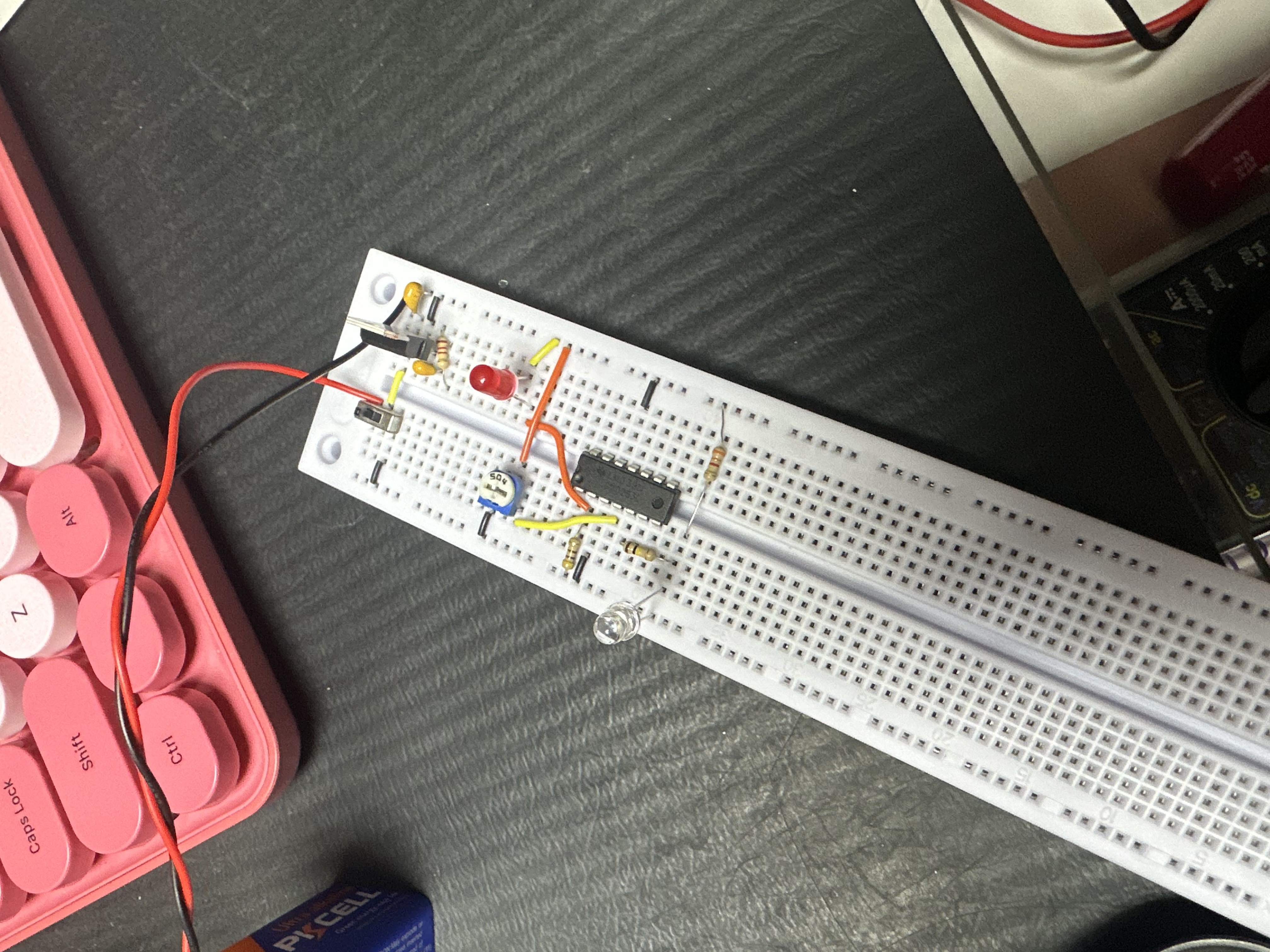
Pink Keyboard Makes Electronics!
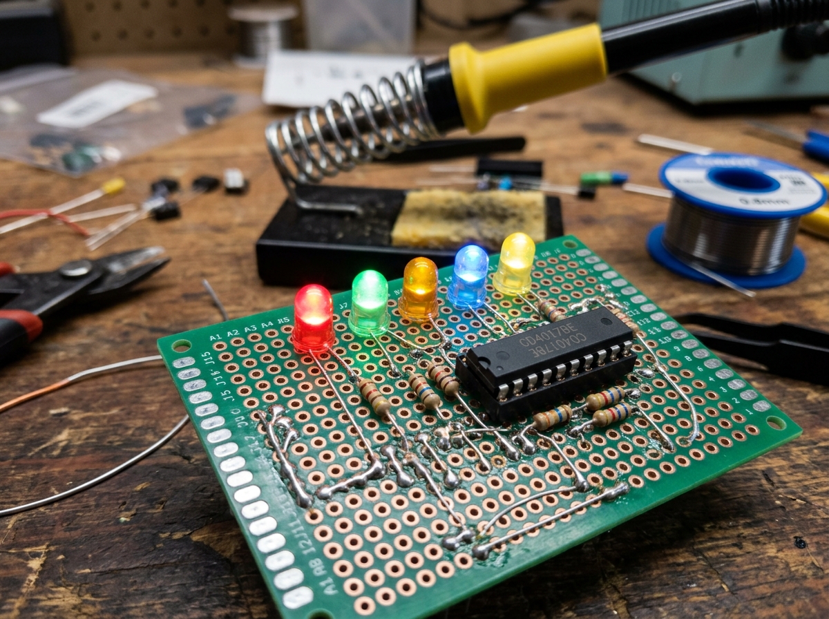
First Soldered Protoboard ā LED Chaser Circuit
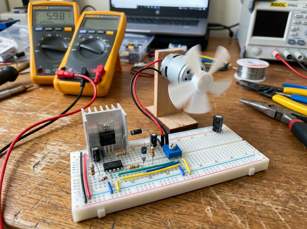
Simple DC Motor Speed Controller with Transistor + Diode
Potentiometer-Controlled Servo Test Rig
Arduino RGB Mood Lamp with PWM Fading
Light-Activated Nightlight Using an LDR and Transistor
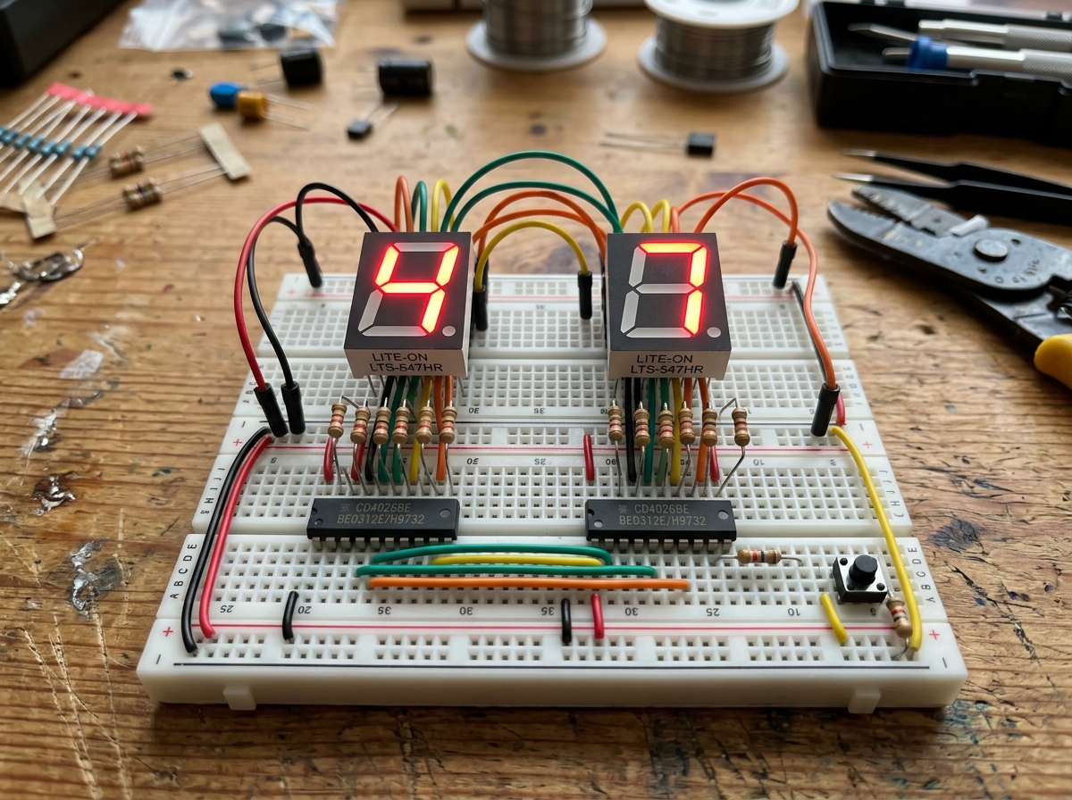
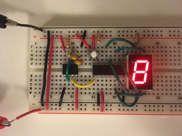
Two-Digit Arduino Event Counter with CD4026
555 Timer Metronome for Guitar Practice
Step-by-Step Project Walkthroughs & Teasers
Watch video experiment guides, circuit lab setups, and hardware prototyping tutorials. Non-subscribers can preview lesson titles and teasers; active subscribers & Digital VIP pass holders get full video access!
Making Electronics Work! (Project #1 Walkthrough)
Soldering Station & Iron Safety Guide
Circuit Prototyping & Noise Filtering Tips
Build-Along Challenge: Transistor Switching
STEM Digital Tools & Electronics Cheat Sheets
Interactive tools, component pinout guides, and lab schematics designed for makers.
šØ Interactive Resistor Color Code Calculator
š Quick Electronics Pinout Reference
Flat face facing you: Pin 1 = Emitter, Pin 2 = Base, Pin 3 = Collector. Max 40V, 600mA.
Notch at top left: 1=GND, 2=Trigger, 3=Output, 4=Reset, 5=Control, 6=Threshold, 7=Discharge, 8=VCC (+5V to +15V).
Silver band on diode = Cathode (-). Long leg on LED = Anode (+), flat edge = Cathode (-).
š Lab Schematics & Code Downloads
Basic LED Resistor & Switch Circuits
Arduino Blink & PWM Control