
I am having difficulty with Experiment 11 in the second edition of Make: Electronics.
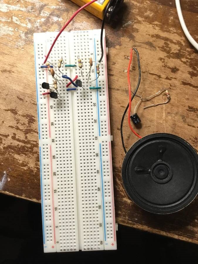
Specifically I am having trouble figuring out where to connect the components in Figure 2-118 to the breadboard. They are meant to replace the 4 color components at the lower right of Figure 2-116 / 2-117.
I am able to generate sound by guessing where to connect the speaker, 100uF capacitor, and 1K resistor, but the capacitor and resistor have no bearing on the sound..... it makes the buzz whether those components are attached or not. Also, replacing the 100uF capacitor with a 1uF capacitor as the upper portion of Figure 2-119 instructs does not change the character of the sound, so clearly I am not putting things in their proper places.
Obviously this is an issue of being able to translate schematics to functional design, but as a complete beginner on page 96 of an introductory electronics book, I find this very difficult.
Could someone please help me figure out Figure 2-118? I also foresee difficulty with the lower portion of Figure 2-119.
Workbench Circuit Photos
TechCrate editorial answer
Bench Answer
The speaker should be in the intended signal path rather than connected directly to an oscillator node. With power disconnected, trace the circuit from the oscillator output through the 1 kΩ resistor, then through the polarized coupling capacitor, then through the speaker to ground. The capacitor blocks the DC component while passing the changing signal; the resistor limits current.
Unlock the full bench walkthrough
Members get the complete diagnostic workflow, every measurement to take and the verification checklist.
Unlock Digital VIP · $4.99/mo →