
Electronic Components Reference Guide
Your comprehensive visual manual for identifying, testing, and implementing essential electronic components. Perfect for students, educators, and makers.
Building circuits is like learning a new language. Before you can read a schematic or construct a prototype, you must understand the individual parts—what they look like, what they do, and how they behave in a circuit. This reference guide covers the fundamental components you'll encounter in almost every electronics project, complete with practical wiring tips and testing procedures.
⚡ Quick Navigation
1. Resistors (Limit Current Flow)
Resistors are the most common components in electronics. Think of them as water restrictors in a pipe: they limit the flow of electrical current. Measured in Ohms (Ω), resistors protect sensitive components from burning out and set the voltage levels across different parts of a circuit.
Common Uses:
- Limiting current to protect LEDs
- Setting voltages in voltage divider circuits
- Pull-up/pull-down lines for digital inputs (like Arduino pins)
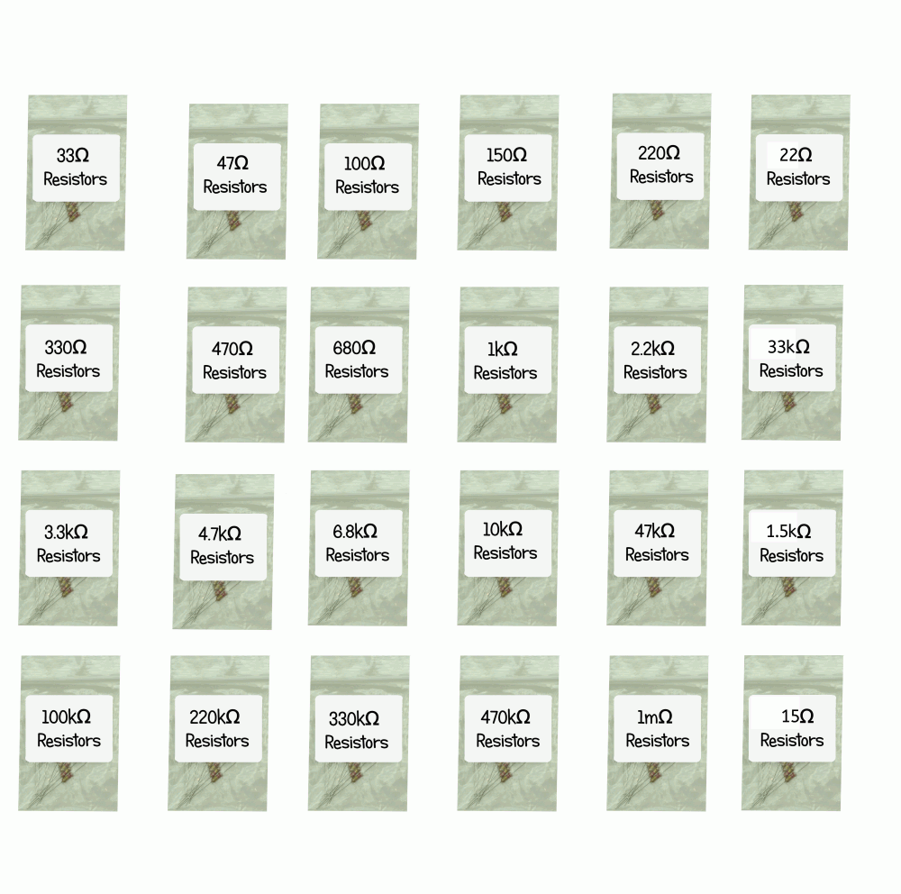 ProTechTrader 235pcs Resistor Assortment
How to Read Resistor Color Bands
Standard through-hole resistors use colored bands to specify their resistance value. The most common are 4-band resistors. To read one, place it so the Gold or Silver band is on the right-hand side, then read from left to right:
| Color | Band 1 (Digit) | Band 2 (Digit) | Band 3 (Multiplier) | Band 4 (Tolerance) |
|---|---|---|---|---|
| Black | 0 | 0 | x 1 | — |
| Brown | 1 | 1 | x 10 | ±1% |
| Red | 2 | 2 | x 100 | ±2% |
| Orange | 3 | 3 | x 1,000 (1k) | — |
| Yellow | 4 | 4 | x 10,000 (10k) | — |
| Green | 5 | 5 | x 100,000 (100k) | ±0.5% |
| Blue | 6 | 6 | x 1,000,000 (1M) | ±0.25% |
| Violet | 7 | 7 | x 10,000,000 | ±0.1% |
| Gray | 8 | 8 | — | — |
| White | 9 | 9 | — | — |
| Gold | — | — | x 0.1 | ±5% |
| Silver | — | — | x 0.01 | ±10% |
Resistor Example Calculation:
If a resistor has bands Brown - Black - Orange - Gold:
• Digit 1: Brown (1)
• Digit 2: Black (0)
• Multiplier: Orange (x 1,000)
• Resistance: 10 x 1,000 = 10,000 Ω = 10kΩ with ±5% tolerance.
Prefer not to do the math by hand? Try our free interactive resistor color-code calculator in the TechCrate Community Hub for instant results.
Need Resistors for Your Workbench?
Get our premium 235-piece resistor kit containing 25 each of the 8 most common values (from 33 Ohm up to 1M Ohm). High precision 5% carbon film resistors.
2. Capacitors (Store Electrical Charge)
Capacitors act like tiny temporary batteries. They store electrical charge when voltage is applied and release it when the voltage drops. Capacitors are measured in Farads—most commonly in microfarads (µF), nanofarads (nF), or picofarads (pF).
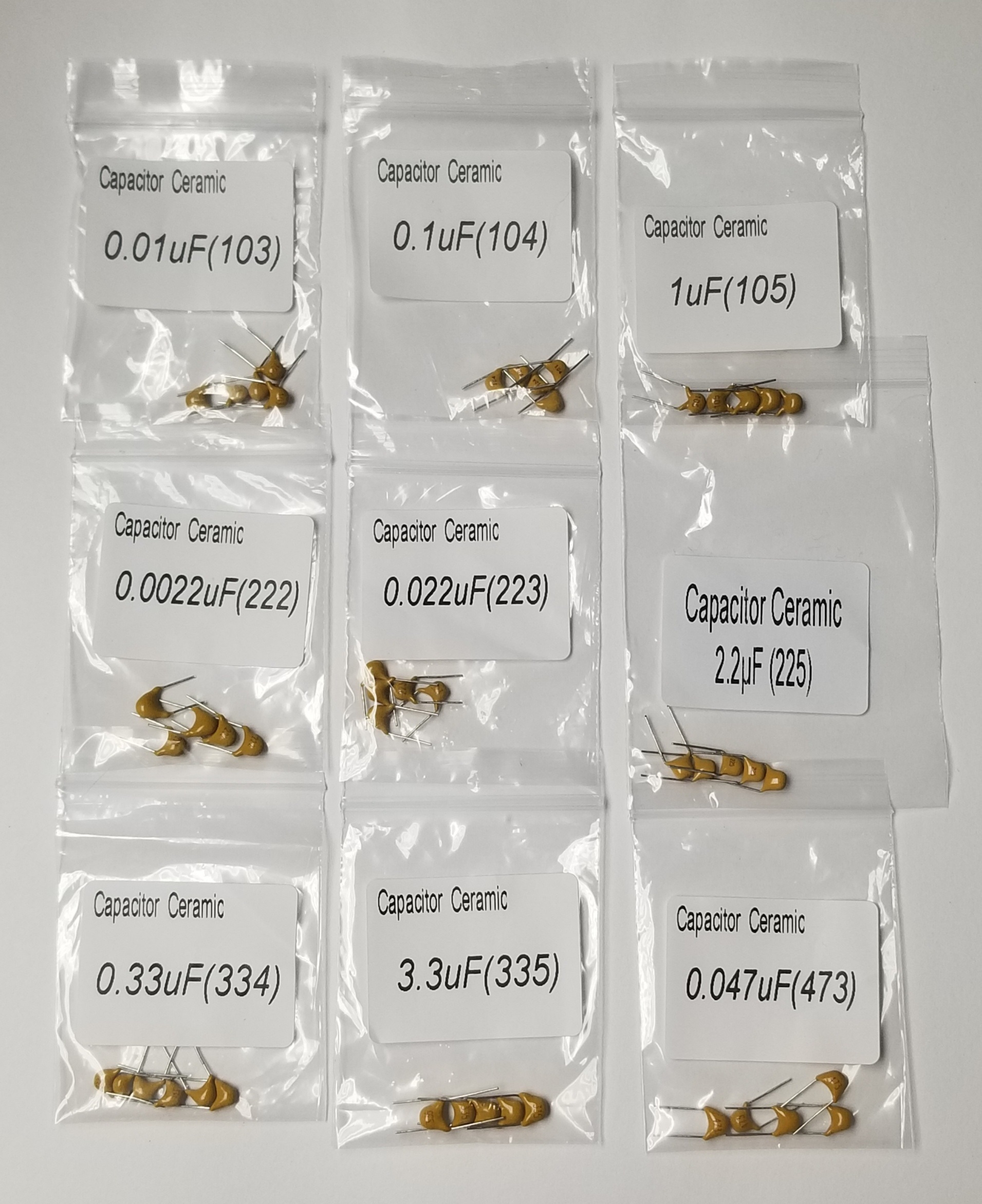
Ceramic Capacitors (Non-Polarized)
These small disc or block-like capacitors are used for high-frequency noise filtering and decoupling. They have no positive or negative polarity and can be installed in either direction safely.
Commonly labeled with a 3-digit code:
"104" = 10 + 4 zeros = 100,000pF = 100nF = 0.1µF
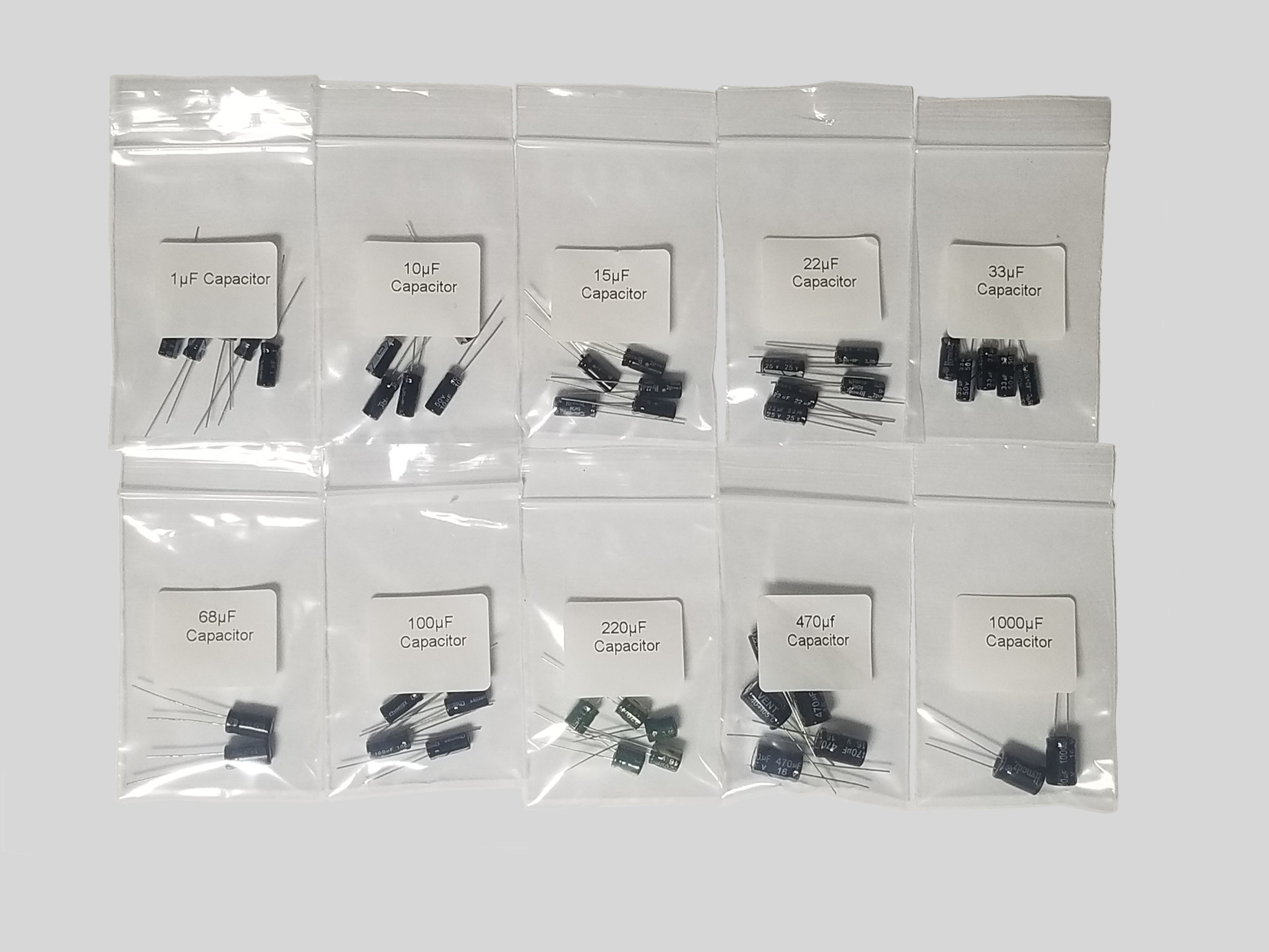
Electrolytic Capacitors (Polarized)
Electrolytic capacitors pack large storage capacity into small cylinders. They are highly polarized and MUST be installed correctly.
3. Diodes & LEDs (One-Way Valves)
A Diode is an electrical one-way valve. It permits current to flow easily in one direction (forward bias) but blocks it from flowing back (reverse bias). Standard silicon diodes typically cause a 0.7V voltage drop when conducting forward.
Anode (+) & Cathode (-): The negative terminal is called the Cathode and is marked on the physical diode body with a painted stripe. Current flows from the positive Anode to the Cathode.
LEDs (Light Emitting Diodes) are diodes that glow when current passes through them. Just like regular diodes, they only work in one direction. The longer pin is the positive Anode, and the flat edge on the colored bulb points to the negative Cathode.
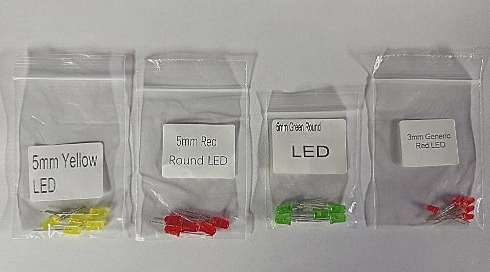 Standard 5mm Red LEDs (Anode (+) lead is longer)
Warning: Always Use a Current-Limiting Resistor with LEDs!
Connecting an LED directly to a power source (like a 9V battery) will instantly draw too much current and burn it out. Always place a resistor in series with the LED. A 220Ω to 470Ω resistor is perfect for 5V power sources, and a 1kΩ resistor is ideal for 9V sources.
4. Transistors (Switches & Amplifiers)
If resistors are the restrictors and diodes are the check valves, Transistors are the electronically controlled valves. They allow a small control voltage or current to switch a much larger current flow. Transistors can act as switches (fully on or off) or as amplifiers (proportional control).
Bipolar Junction Transistors (BJTs)
BJTs are current-controlled switches. A tiny current flowing into the Base pin allows a much larger current to flow from the Collector to the Emitter. Common types include:
- 2N3904 (NPN): Turns ON when control signal is HIGH. Standard for low-power switching.
- 2N3906 (PNP): Turns ON when control signal is LOW.
Field-Effect Transistors (MOSFETs)
MOSFETs are voltage-controlled switches. Applying a voltage to the Gate pin creates an electric field that lets current flow between the Drain and Source pins. Because they require virtually zero control current, they are highly efficient and ideal for high-power devices like motors.
- IRF540N: A beefy N-channel MOSFET capable of switching up to 33A at 100V. Perfect for Arduino motor control.
5. Integrated Circuits / ICs (Complete Micro-Circuits)
An Integrated Circuit (IC), or silicon chip, packs thousands of tiny transistors, diodes, and resistors into a single block of plastic. ICs are built to perform complex functions, from amplifying audio to serving as full computers (microcontrollers).
Identifying Pin 1 Orientation: ICs must be installed in the correct direction. Look for a circular dimple (indentation) or a semi-circular notch on one end of the plastic casing. Pin 1 is located directly to the left of this notch. Pins are numbered counterclockwise starting from Pin 1 when looking from the top.
⚡ The Legend of Pin 1:
Placing an IC backward in a powered circuit will reverse its power rails, instantly destroying the internal silicon and potentially overheating the chip. Always double-check that the notch on the IC matches the notch on your circuit diagram or socket.
6. Prototyping Hardware & Switches
To connect all these components together without messy soldering, makers use solderless breadboards and mechanical switches.
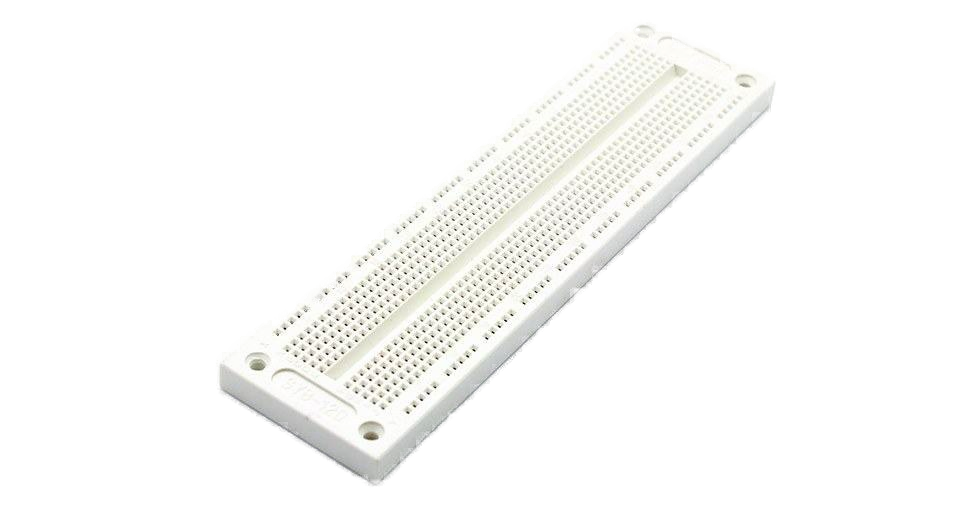 ProTechTrader 700-Point solderless breadboard
Solderless Breadboards
A breadboard is the testing ground for circuits. Inside the plastic housing are rows of metal clips. Pushing a component wire into a hole secures it and links it to everything else in that vertical row of 5 holes.
- Outer Rails (Power Bus): Horizontal rows marked with red (+) and blue (-) lines are used to distribute power across the board.
- Center Columns (Terminal Strips): Vertical rows of 5 connected holes, split by a center divider notch (intended for DIP ICs).
Tactile Pushbutton Switches
Mechanical switches complete or interrupt a circuit's path. A Tactile Pushbutton is a momentary switch that makes electrical contact only when pressed. They typically have 4 pins which are internally linked in pairs; pressing the button connects the two pairs together.
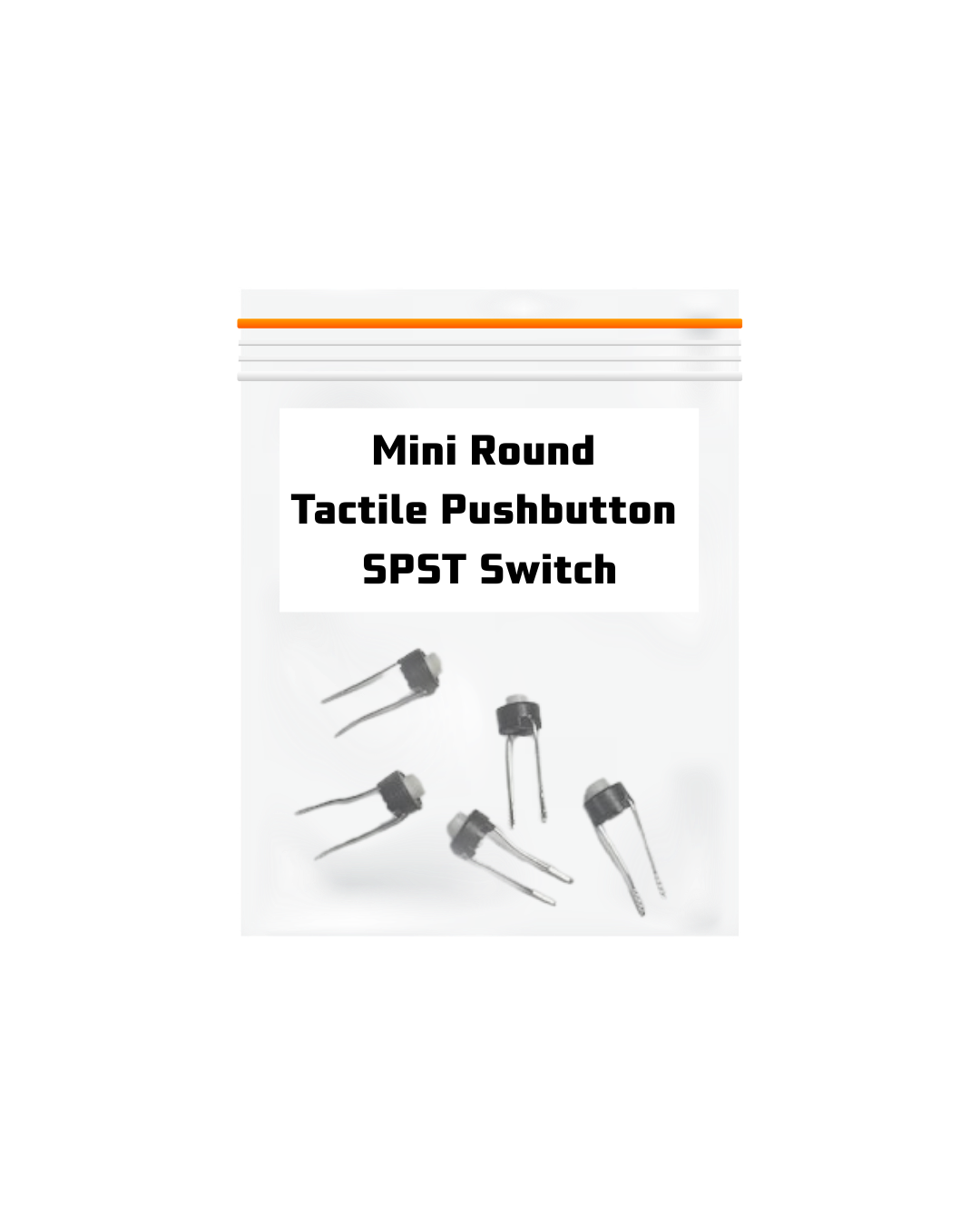 Tactile Micro Pushbutton Switch
7. Testing Components with a Multimeter
A Digital Multimeter (DMM) is the ultimate diagnostics tool. It allows you to verify components are working before placing them in a circuit.
How to Test a Resistor:
Turn the dial to the Ohms (Ω) setting. Place one probe on each leg of the resistor (it doesn't matter which color probe). The screen should read within 5% of the color bands. A reading of infinity indicates the resistor has failed "open".
How to Test a Diode or LED:
Set the dial to Diode Mode (indicated by a triangle pointing to a line). Connect the Red probe to the Anode (positive leg) and the Black probe to the Cathode (negative leg). A good silicon diode will read a voltage drop of 0.5V to 0.7V. Reverse the probes—it should display "OL" (Open Loop).
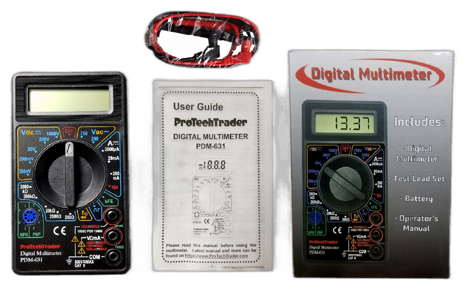 ProTechTrader 7-Function Digital Multimeter
Essential ProTechTrader Gear
Make: Electronics Kits (3rd Ed)
Get the official partner kits hand-selected and approved by author Charles Platt. Everything you need for the updated 2023 3rd Edition.
Beginner's Tool Kit
Set up your electronics bench with our complete set, featuring a 30W soldering iron, solder wire, stand, and our 7-function digital multimeter.
Shop ProTechTrader on Your Favorite Marketplace
You can find our high-quality components and official educational kits on your preferred shopping platforms:
- Official Website: ProTechTrader.com (Get the best prices, direct support, and complete inventory selection)
- Amazon: ProTechTrader Official Amazon Store (Prime shipping options available)
- eBay: ProTechTrader eBay Store (Over 15,100+ sales with 99.7% positive customer feedback)
The ProTechTrader Promise
As a small family-owned business based in New Jersey, we care deeply about your electronic builds and educational journeys. Whether you're a beginner maker, STEM educator, or experienced engineer, we test every kit and support every customer directly.
Trusted by Customers
See verified real customer reviews on Google Shopping
